Key takeaways
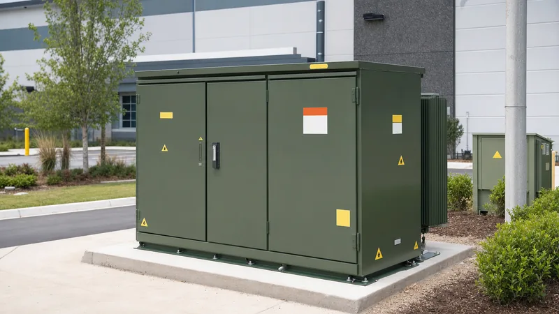
- An electrical transformer box houses a step-down distribution transformer inside a tamper-resistant, grounded steel enclosure designed for public, street-level installation.
- Dead-front configurations using 200 A loadbreak or 600 A deadbreak elbows eliminate exposed energised conductors, providing superior operator safety compared to live-front designs.
- Loop-feed systems equipped with internal multi-position oil switches enable continuous service during maintenance by isolating faulted cable sections without interrupting downstream customers.
- Underground transformer box installations require strict adherence to IEEE C57.12.28 or IEC 62271-202 containment, earthing, and anti-corrosion coating standards.
- Siting clearances require at least 3.0 m (10 ft) from combustible building walls and non-combustible doors to guarantee fire safety and adequate airflow for natural convective cooling.
Quick answer: An electrical transformer box (commonly known as a pad-mounted transformer or ground-level enclosure) is a tamper-resistant outdoor steel enclosure containing a liquid-immersed or dry-type distribution transformer that steps down medium-voltage distribution power to low utilisation voltages for commercial and residential consumers.
In modern underground power distribution architectures, urban planners and electrical utilities have phased out vulnerable overhead crossarms in favour of ground-level infrastructure. Sited on public pavements, suburban greenbelts, and commercial parking bays, these installations route feeder lines safely beneath the soil. Siting a high-voltage apparatus in areas accessible to the public introduces severe electrical safety, mechanical durability, and environmental isolation challenges. Understanding the internal topology, switching configurations, and constructional integrity of a power transformer box is essential for consulting engineers, utility contractors, and procurement professionals seeking compliance with international grid codes such as IEEE C57.12 series or IEC standards. For broader distribution network context, review our technical overview on transformers electricity distribution systems.
What Is an Electrical Transformer Box and How Does It Operate?
An electrical transformer box operates as an outdoor distribution node that steps medium-voltage incoming current down to domestic and commercial service levels through inductive magnetic transformation inside a self-contained, lockable cabinet. The unit replaces pole-mounted hardware by coupling subterranean cable networks directly to a locked, grounded apparatus located at ground level.
Commonly referred to colloquially as a street transformer, this equipment receives a primary distribution voltage—typically between 11 kV and 34.5 kV—via subterranean insulated cables. The internal core-and-coil assembly, usually immersed in mineral oil or synthetic ester fluid, couples the primary windings to secondary windings using electromagnetic induction governed by Faraday’s law. The secondary terminals output three-phase or single-phase utilisation voltages (such as 400/230 V in IEC jurisdictions or 480Y/277 V and 208Y/120 V in 60 Hz ANSI/IEEE regions). To explore the internal magnetic core architectures that drive these enclosures, see our detailed guide to transformers internal components.
Because public access is inevitable, the design segregates the internal transformer fluid tank from the cable connection bays. The outer cabinet is separated into high-voltage (HV) and low-voltage (LV) compartments behind locked, interlocked doors. In addition to voltage transformation, the cabinet houses protective fuses, oil-immersed loadbreak switches, and surge arresters within the same footprint, eliminating the need for detached switchgear housings in standard utility configurations.
Underground Transformer Box vs Pad-Mounted Enclosure Architecture
An underground transformer box differs fundamentally from a surface pad-mounted enclosure in its physical placement, water ingress protection, and thermal dissipation mechanisms. While a pad-mounted unit rests on a raised concrete plinth above ground, a true subterranean vault transformer operates fully or partially submerged beneath street pavement grade.
Subsurface vaults require submersible units compliant with IEEE C57.12.24 standards. These tanks are constructed from continuous-welded 304 or 316L stainless steel, capable of operating while fully immersed in floodwaters, with hermetically sealed bushings and dry nitrogen headspaces. Conversely, the common pad-mounted underground transformer box seen along suburban streets is a surface-level installation compliant with IEEE C57.12.28 or IEC 62271-202. The cabinet relies on natural air convection across external radiator panels or corrugated cooling walls to maintain temperature rises within standard limits (such as 65 °C rise over a 30 °C average ambient).
Internally, pad-mounted enclosures are categorized into two primary electrical terminal topologies: dead-front and live-front architectures. In modern installations, dead-front configurations are standard:
- Dead-front architecture: Utilises fully shielded, insulated, and submersible elbow connectors plugged into welded transformer bushings. When the cabinet door is open, no exposed energised parts exist in the HV compartment. Technicians can safely operate disconnects and test voltage with hot sticks.
- Live-front architecture: Features exposed porcelain bushings with mechanical lugs in the HV compartment. This older design requires de-energisation of the entire upstream line or elaborate live-line safety clearances before an operator can access the cabinet.
For comparative engineering specifications across global markets, consult our analysis of pad-mounted transformers ANSI vs IEC designs.
Connecting the Transformer Box Power Line: Radial vs Loop Feed
Connecting a transformer box power line is executed via either a radial or a loop-feed medium-voltage network scheme, with loop feed offering substantially higher operational resilience. The choice determines the internal bushing arrangement, internal switching mechanisms, and downstream fault-clearing capabilities.
In a radial feed network, a single subterranean MV cable enters the transformer’s high-voltage compartment and terminates directly at the primary bushings. If a fault occurs on the feeder line upstream, the transformer and all associated loads lose power until the cable is physically excavated and repaired. Radial designs require only three HV bushings for a three-phase system (or one/two for single-phase).
In contrast, a loop-feed architecture incorporates six HV bushings arranged in an A-side and B-side layout (two bushings per phase, labelled H1A/H1B, H2A/H2B, H3A/H3B). The utility feeder enters through one side, connects to the internal bus, and exits through the other side to feed the next street transformer in the series. Operators utilise an internal, oil-immersed four-position rotary loadbreak switch. This switch provides four operational states: A-side only, B-side only, A and B in parallel, or open. If a cable fault develops between two transformer boxes, field technicians can open the faulted section via the loadbreak elbows and energise the unit from the opposite direction of the loop, restoring service within minutes.
Key Technical Specifications and Engineering Parameters
Electrical transformer boxes are specified according to rated apparent power, insulation ratings, impedance, and internal protection devices. Selecting the appropriate parameters guarantees adequate short-circuit withstand and thermal life expectancy under varying continuous loads.
The following engineering parameters demonstrate standard industry ratings for commercial three-phase and residential single-phase pad-mounted transformers:
| Engineering Parameter | Three-Phase Commercial Box | Single-Phase Residential Box | Standard / Metric |
|---|---|---|---|
| Power Rating | 75 kVA to 5,000 kVA | 10 kVA to 167 kVA | kVA (Continuous 65 °C Rise) |
| Primary Voltage Range | 2.4 kV to 34.5 kV | 2.4 kV to 19.9 kV (Line-to-Ground) | kV (Nominal) |
| Basic Impulse Level (BIL) | 60 kV to 150 kV | 60 kV to 125 kV | kV Crest (Peak Withstand) |
| Secondary Voltage | 208Y/120 V, 480Y/277 V, 400 V | 120/240 V (Split Phase) | Volts (RMS) |
| Percent Impedance (%Z) | 2.5% to 5.75% | 1.5% to 3.0% | % at Reference Base Temperature |
| Core Construction | Cold-rolled grain-oriented silicon steel or Amorphous | Wound core silicon steel | Magnetic Material |
| Dielectric Fluid | Mineral Oil (Type II) or FR3 Synthetic Ester | Mineral Oil or Natural Ester | Dielectric Breakdown > 30 kV |
| Enclosure Rating | IEEE C57.12.28 / NEMA 3R / IP54 | IEEE C57.12.28 / NEMA 3R / IP54 | Tamper-Resistant Spec |
| Overcurrent Protection | Bay-O-Net fuse with current-limiting back-up | Bay-O-Net or dual-element fuse | Expulsion / Partial-range CLF |
Accurate sizing prevents premature insulation degradation caused by winding hotspots. You can verify network kVA demands against upstream transmission feeder limits by reviewing our transmission transformer engineering guide.
Installation and Siting Requirements for an Underground Transformer
Installing an underground transformer requires precise structural civil works, adherence to fire separation distances, and low-impedance earthing grid integration to maintain public safety. Failure to follow civil clearance envelopes introduces fire propagation risks and restricts maintenance access.
Civil and electrical site teams execute the commissioning workflow through this sequential engineering procedure:
- Excavation and foundation grading: Excavate the installation footprint down to undisturbed soil below the local frost line. Lay a compacted base course of crushed stone (150 mm minimum thickness) to ensure positive drainage beneath the pad.
- Concrete plinth casting: Pour a reinforced concrete pad (compressive strength minimum 28 MPa / 4,000 psi) with an open conduit window designed to accept primary and secondary sweeps. Ensure the pad sits at least 50 mm to 100 mm above final surrounding grade to prevent stormwater ponding.
- Earthing grid installation: Drive a minimum of two copper-bonded earthing rods (16 mm diameter by 3.0 m length) located diagonally at opposite corners of the pad. Bond these via bare stranded copper conductor (typically 70 mm² or 2/0 AWG) directly to the external grounding pads of the transformer tank and cabinet enclosure, verifying a total ground resistance of less than 5 ohms.
- Conduit pulling and box positioning: Pull medium-voltage and low-voltage conductors through designated cable sweeps. Rig and position the electrical transformer box onto the cured pad using certified lifting eyes, ensuring weight is evenly distributed without deflecting the cabinet sill.
- Terminations and compartment segregation: Terminate MV cables using shielded dead-front loadbreak elbow connectors onto the well bushings. Bolt secondary low-voltage conductors to tin-plated copper spade terminals using calibrated torque wrenches according to manufacturer specifications.
- Pre-commissioning electrical testing: Conduct insulation resistance (megohmmeter) testing at 2.5 kV or 5 kV DC, perform winding resistance measurements, confirm voltage ratios, and execute dielectric breakdown tests on an oil sample prior to primary energisation.
Safety, Enclosure Integrity, and Tamper Resistance Standards
Safety standards mandate that any power transformer box placed in public rights-of-way must resist intentional physical intrusion, pry attacks, moisture entry, and internal arcing faults. The benchmark performance standard globally is IEEE C57.12.28 (pad-mounted equipment enclosure integrity) alongside regional IEC protection ratings.
Enclosure panels are formed from 12-gauge or 14-gauge structural steel (or marine-grade 304L stainless steel for coastal environments). Joints are fully welded or internally bolted to present a flush exterior devoid of exposed external hardware, screws, or removable pins. The doors feature captive penta-head security bolts requiring specialised utility sockets to loosen, paired with recessed provisions for heavy-duty master padlocks.
Under IEEE C57.12.28 testing, the cabinet must withstand rigorous mechanical abuse without allowing physical entry:
- Pry testing: A pry bar applying a torque of 102 Nm (75 ft-lbs) against every cabinet seam, latch, and hinge must not open a gap wider than 6.35 mm (0.25 in), preventing the insertion of wires or screwdrivers into energised spaces.
- Pull and push tests: Door handles and locking mechanisms must survive 400 N static forces applied in all directions.
- Corrosion resistance: Enclosures must pass a 1,000-hour salt spray test (ASTM B117) and cross-hatch adhesion testing (ASTM D3359) to prevent wall thinning and rust formation that could degrade structural containment over a 30-year design life.
Next steps: specifying and sourcing
Specifying the optimal electrical transformer box requires providing comprehensive site-specific operational parameters to the factory engineering team. When preparing your request for quotation, submit the required nominal kVA capacity, primary and secondary system voltages, basic impulse insulation level (BIL), dead-front versus live-front terminal styles, loop or radial network feed, and specific enclosure metallurgy (carbon steel or 304L stainless steel for C5 marine environments).
Review our factory-engineered pad-mounted transformers and compact transformer substations to match your distribution network layouts. For custom engineering drawings, short-circuit withstand verification, or project pricing, submit your load schedules and single-line diagrams directly through our transformer quotation portal.
Frequently asked questions
What is the green box in front of my house called?
The green box is an electrical transformer box, formally called a pad-mounted transformer. It steps down high-voltage underground power line electricity from utility distribution levels (such as 13.8 kV) to split-phase 120/240 volts used safely inside residential homes.
Why does an electrical transformer box make a humming noise?
The humming noise is caused by magnetostriction, where the internal silicon steel core sheets physically expand and contract twice during every alternating current cycle. This mechanical vibration transfers through the dielectric cooling oil to the steel tank panels, creating an audible hum at 100 Hz or 120 Hz.
How close can you landscape or build near a street transformer?
Utility regulations typically mandate maintaining at least 3.0 metres (10 feet) of clear, unobstructed space directly in front of the cabinet access doors, and 0.9 to 1.5 metres (3 to 5 feet) around the sides and rear. These clearances allow field crews to open the doors fully and safely use hot sticks during maintenance.
Is it dangerous to touch an underground transformer box?
It is safe to touch the exterior of an undamaged, properly locked pad-mounted transformer box because the outer metal casing is mechanically grounded. However, climbing on, sitting on, or attempting to pry open the box is extremely dangerous due to the lethal medium-voltage cables running inside.
What happens if an electrical transformer box gets flooded?
Standard pad-mounted transformer boxes are weather-resistant against rain but are not designed for full submersion. If floodwaters submerge the internal cabinet components, water can enter low-voltage terminals or compromise seals, triggering phase-to-ground faults that activate upstream fuses to isolate the unit automatically.
Tags: electrical transformer box underground transformer street transformer power transformer box pad-mounted transformer


