Key takeaways
- A grounding transformer provides an artificial neutral for ungrounded delta systems to permit system grounding and ground-fault current return.
- The zigzag transformer configuration cancels zero-sequence flux in the core limbs, yielding low zero-sequence impedance without needing a secondary winding.
- Continuous kVA ratings for earthing transformers are typically only 3% to 10% of their short-time fault rating, which substantially reduces equipment footprint and cost.
- Zero-sequence impedance verification is governed by IEC 60076-6 clause 8.6 and IEEE C57.32 to validate proper fault current limitation.
- Integrated auxiliary secondary windings can supply local substation low-voltage loads while the primary winding performs system grounding.
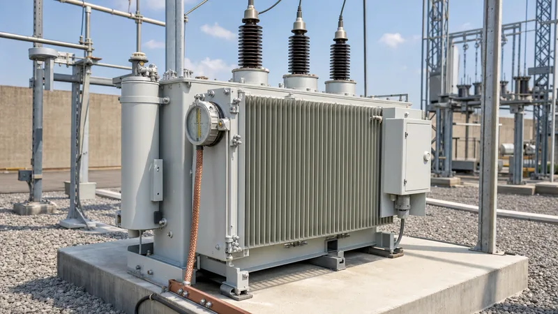
Quick answer: A grounding transformer is an electrical device designed to provide a physical neutral point for an ungrounded three-phase power system, facilitating system earthing and ground-fault clearing. By creating a low-impedance return path for zero-sequence currents, it stabilizes neutral voltage and suppresses dangerous transient overvoltages caused by arcing ground faults.
Industrial plants, wind farms, solar collector substations, and distribution networks frequently operate three-phase medium-voltage circuits fed from delta-connected transformer windings. While an isolated delta network can operate continuously with a single line-to-ground fault, intermittent arcing faults on ungrounded systems generate restriking transients that produce phase-to-ground overvoltages exceeding 300% to 400% of nominal voltage. Installing a grounding transformer establishes an engineered zero-sequence path, transforming an ungrounded network into an effectively grounded or resistance-grounded network compatible with selective protection relays.
What Is a Grounding Transformer and Why Is It Required?
A grounding transformer provides an engineered neutral point on an ungrounded power system where no physical neutral exists, such as the secondary side of a delta-connected transformer. According to IEEE 142 (the Green Book) and IEEE C57.32, ungrounded medium-voltage distribution systems remain susceptible to catastrophic phase-to-phase flashovers caused by capacitive charge buildup during single line-to-ground faults. Connecting an earthing device resolves this vulnerability by stabilizing phase voltages relative to ground potential under steady-state and faulted conditions.
Without a grounding transformer, a line-to-ground fault forces the healthy phase conductors to experience full line-to-line voltage against earth. This voltage elevation subjects cable insulation, surge arresters, and motor terminations to sustained dielectric stress. Modern industrial installations and collector systems designed for the grid integration of renewable energy sources mandate grounding transformers to ensure protective relays quickly isolate phase-to-ground disturbances and prevent extensive thermal damage to downstream electrical assets.
Zig Zag Transformer vs Wye-Delta Grounding Configuration
System designers choose between a zig zag transformer (interconnected star) and a conventional wye-delta transformer based on footprint, cost, and auxiliary power requirements. A zigzag transformer consists of six coils arranged on a three-legged iron core, with two winding halves from different phases wound in opposition on each limb. When positive-sequence or negative-sequence currents pass through the core during balanced normal operation, the windings produce equal and opposite magnetic fluxes, resulting in high magnetising impedance and negligible no-load losses.
Conversely, zero-sequence fault currents flow in the same direction in all three lines. In a zig zag grounding transformer, these currents divide equally between the split windings on each leg, cancelling out the net core flux and providing an extremely low zero-sequence impedance. A wye-delta earthing transformer achieves a similar effect by circulating zero-sequence current within its closed delta secondary winding. However, the zigzag configuration requires approximately 15.5% less physical core and copper active material for the same short-time thermal rating because it achieves phase flux cancellation without a dedicated secondary closed loop.
| Criterion | Zigzag Grounding Transformer (Zn) | Wye-Delta Earthing Transformer (Yd) |
|---|---|---|
| Winding Configuration | Interconnected star (split phase per limb) | Wye primary with closed delta tertiary |
| Secondary Auxiliary Power | Optional (requires added secondary coils) | Inherent (available from delta or tertiary) |
| Zero-Sequence Impedance Control | Controlled by internal winding leakage reactance | Controlled by inter-winding leakage impedance |
| Footprint and Core Mass | Compact (approx. 15% lower weight) | Standard distribution core frame |
| Cost Basis | Lowest capital cost for pure earthing duty | Higher capital cost; dual-purpose flexibility |
| Application Standard | IEC 60076-6, IEEE C57.32 | IEC 60076-1, IEEE C57.12.00 |
Sizing and Thermal Ratings: Worked Calculation Example
A zigzag earthing transformer is primarily specified by its system operating voltage, continuous neutral current, short-time neutral fault current, and fault duration in seconds. Because phase-to-ground faults in medium-voltage systems are cleared rapidly by upstream switchgear, earthing transformers carry intermittent, short-time thermal ratings (typically 10 seconds or 60 seconds) rather than continuous high-current ratings.
Consider an ungrounded 13.8 kV, 50 Hz industrial distribution bus requiring a neutral grounding system limited to a line-to-ground fault current of 400 A for a maximum clearing time of 10 seconds. The line-to-neutral voltage ($V_{LN}$) is calculated as:
$$V_{LN} = \frac{13800\text{ V}}{\sqrt{3}} \approx 7967.4\text{ V}$$
To provide 400 A of total neutral fault current ($I_N$), each phase winding of the earthing transformer carries one-third of the total return current ($I_0 = I_N / 3 = 133.3\text{ A}$). The required zero-sequence impedance per phase ($Z_0$) is determined by:
$$Z_0 = \frac{3 \times V_{LN}}{I_N} = \frac{3 \times 7967.4\text{ V}}{400\text{ A}} = 59.76\ \Omega/\text{phase}$$
The short-time apparent power rating ($kVA_{short-time}$) of the earthing transformer equals the phase-to-neutral voltage multiplied by the total neutral current:
$$kVA_{short-time} = \frac{V_{LN} \times I_N}{1000} = \frac{7967.4\text{ V} \times 400\text{ A}}{1000} \approx 3187\text{ kVA}$$
In accordance with IEEE C57.32 clause 6.2, an earthing transformer with a 10-second thermal rating has a continuous equivalent rating between 3% and 10% of its short-time capability, depending on winding thermal dissipation. For this 3187 kVA 10-second design, an equivalent continuous thermal capability of 100 kVA to 150 kVA is standard, drastically decreasing the required tank dimensions and oil volume compared to a continuously rated 3.15 MVA distribution unit.
Auxiliary Loading and Neutral Grounding Resistor Integration
System engineers frequently integrate a Neutral Grounding Resistor (NGR) between the grounding transformer neutral bushing and substation earth grid to define system fault levels precisely. When a solid zero-sequence path yields excessive fault currents that challenge cable thermal limits, an external stainless steel grid NGR inserts resistance into the neutral path, suppressing fault currents to standard thresholds such as 200 A, 400 A, or 1000 A.
When combined with an external resistor, the internal zero-sequence reactance ($X_0$) of the grounding transformer must remain low relative to the resistor value ($R_N$). This ensures that the fault magnitude and system damping are governed predominantly by the linear resistor rather than non-linear reactive components. Many project specifications also request an auxiliary secondary winding (typically 400 V or 480 V low-voltage star) integrated onto the same core. This dual-purpose design allows the earthing transformer to simultaneously establish the MV neutral and deliver continuous station auxiliary power for substation battery chargers, motor-operated disconnectors, and cooling fans, eliminating the expense of a standalone auxiliary service transformer.
Protection Schemes for a Grounding Transformer
Protecting a grounding transformer requires specialized relay schemes sensitive to zero-sequence thermal accumulation, internal phase-to-phase faults, and prolonged earth faults. Standard three-phase overcurrent relays configured on the primary feeders will not clear low-magnitude neutral faults governed by high-impedance paths. Comprehensive protection schemes are detailed in our transformer protection engineering guide and substation protection engineering guide.
The baseline protection architecture includes:
- Neutral Time-Overcurrent Relay (51N/51G): Connected to a current transformer located on the neutral conductor to clear sustained system ground faults before the short-time thermal limit (e.g., 10 seconds) of the windings or NGR is exceeded.
- Phase Overcurrent Protection (50/51): High-voltage phase current transformers detect internal inter-turn or phase-to-phase flashovers on the zigzag core.
- Restricted Earth Fault (REF / 64R): Low- or high-impedance differential protection measuring the balance between phase residual current and neutral bushing current, providing instantaneous tripping for winding earth faults.
- Thermal Overload and Mechanical Detection (49 / 63): Winding temperature simulators paired with sudden pressure relays (or Buchholz gas detection on liquid-immersed units) ensure physical containment during internal arcing.
Testing, Factory Acceptance, and Inspection Checklist
Factory acceptance testing (FAT) for a grounding transformer verifies dielectric withstand, winding continuity, and zero-sequence impedance values per IEC 60076-6 clause 8. Prior to shipment and energisation, engineers follow structured testing procedures aligned with our transformer maintenance engineering guide.
- Insulation Resistance and Polarisation Index: Measure high-voltage windings to ground and phase-to-phase using a 5 kV insulation tester, confirming PI values above 2.0.
- Winding Resistance Measurement: Measure all zig and zag coil sections across phases using a low-resistance digital ohmmeter to confirm phase balance within 1.0% tolerance.
- Zero-Sequence Impedance Measurement: Paralleling the three high-voltage phase terminals and applying a single-phase AC test voltage between the shorted phases and the neutral bushing. Calculate zero-sequence impedance per phase using $Z_0 = 3 \times (V_{test} / I_{test})$.
- Power Frequency Overvoltage Withstand: Perform separate source AC withstand and induced overvoltage testing to confirm inter-turn insulation integrity under elevated phase-to-earth stress.
- Auxiliary Secondary Ratio and Vector Group Verification: Validate the phase displacement between primary and secondary windings (e.g., ZNyn11 or ZNd11) using a standard digital turn ratio meter.
Next steps: specifying and sourcing
When preparing an RFQ for an earthing transformer, provide the system nominal voltage, basic impulse level (BIL), continuous neutral current, short-time neutral current with duration (e.g., 400 A for 10 s), maximum allowable zero-sequence impedance, and auxiliary secondary requirements. Explore our range of oil-immersed transformers and cast-resin dry-type transformers tailored for utility and industrial applications. Submit your project single-line diagrams to our technical department via our transformer quotation page or reach out through our contact page for tailored engineering evaluations.
Frequently asked questions
What is the primary function of a grounding transformer?
A grounding transformer provides an intentional neutral point for an ungrounded electrical system. This neutral allows ground fault current to flow so protective relays can rapidly trip circuit breakers during phase-to-ground faults, preventing severe transient overvoltages.
Can a grounding transformer supply low-voltage auxiliary power?
Yes, grounding transformers can be manufactured with a star- or delta-connected secondary winding. This secondary winding operates simultaneously with the grounding function to supply power to local substation distribution boards, lighting, and cooling equipment.
Why is a zigzag transformer preferred over a standard wye-delta transformer for earthing?
A zigzag transformer cancels zero-sequence flux within its opposing phase coils on each core limb, eliminating the need for a secondary delta winding. This reduces active core and winding weight by approximately 15%, lowering overall equipment cost and installation footprint.
How long can a grounding transformer carry fault current?
Most grounding transformers carry a short-time rating of 10 seconds or 60 seconds according to IEEE C57.32. Upstream protective relays and circuit breakers are coordinated to disconnect the faulted circuit well within this designated thermal window.
What is zero-sequence impedance in an earthing transformer?
Zero-sequence impedance is the effective resistance and inductive reactance the transformer presents to zero-sequence fault currents flowing from the phase lines to the neutral. It dictates the magnitude of earth fault current when no neutral resistor is present.
Is a neutral grounding resistor always required with a grounding transformer?
No, a neutral grounding resistor is optional. If the grounding transformer is designed with sufficient internal zero-sequence reactance, it can be solidly grounded; however, an external resistor is commonly added to limit fault currents to precise levels like 200 A or 400 A.
Tags: grounding transformer zig zag transformer zigzag transformer zig zag grounding transformer zigzag earthing transformer


