Key takeaways
- Substation protection systems isolate electrical faults within 30 to 100 milliseconds to preserve grid stability and prevent asset destruction.
- Modern digital substations implement IEC 61850-8-1 GOOSE messaging and IEC 61850-9-2 Sampled Values to eliminate hundreds of copper hardwires between yard equipment and relay panels.
- Current transformer saturation poses the primary risk to differential protection security, requiring knee-point voltage verification in accordance with IEC 61869-2.
- Optical arc flash detection integrated with feeder relays reduces total fault clearing time from 80 milliseconds to under 12 milliseconds, mitigating severe blast energy.
- Protection zones must overlap precisely around circuit breakers to prevent un-cleared blind spots during high-magnitude short circuits.
Quick answer: Substation protection is an automated network of instrument transformers, protective relays, circuit breakers, and communications architectures designed to detect abnormal electrical conditions and isolate faulted power apparatus within milliseconds. This coordinated system prevents catastrophic equipment failure, mitigates arc flash hazards to personnel, and maintains wider power grid synchronism.
In electrical power infrastructure, substations serve as critical switching and transformation nodes connecting generation, transmission, and distribution assets. When insulation fails, lightning strikes, or mechanical disruptions occur, short-circuit currents can escalate from normal load levels to exceeding 40 kA in less than 5 milliseconds. Without an engineered substation protection scheme, these high fault currents cause severe thermal damage, explosive tank ruptures, and widespread regional blackouts.
Achieving absolute reliability requires combining high-speed numerical relays, redundant battery trip circuits, precise instrument transformers, and standardised communication protocols. Understanding the functional layout and interdependencies of substation protection and control equipment is essential for design consultants, commissioning engineers, and utility operators responsible for modernising medium-voltage and high-voltage assets.
Architecture of Substation Protection and Control
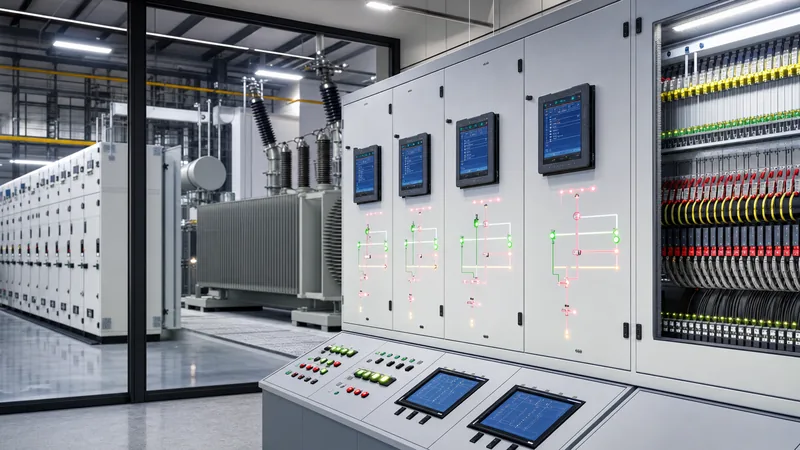
A modern substation protection and control system is structured across three distinct operational layers: the process level, the bay level, and the station level.
The process level comprises the physical switchgear, instrument transformers (current transformers [CTs] and voltage transformers [VTs]), merging units, breaker operating mechanisms, and surge arresters located in the switchyard or switchgear hall. This equipment interfaces directly with high-voltage conductors. In conventional systems, point-to-point hardwired copper cables carry 1 A or 5 A secondary currents and 110 V secondary voltages from the switchyard to relay panels housed inside a sheltered building. In modernised facilities, prefabricated enclosures protect these sensitive interfaces, as detailed in our guide to substation control house modular design.
The bay level consists of intelligent electronic devices (IEDs) dedicated to discrete primary units, such as a single transformer, incoming feeder, or bus coupler. Each bay-level IED runs protection algorithms (such as distance, overcurrent, or differential elements), executes local control commands, and communicates with adjacent bays. The station level hosts human-machine interfaces (HMIs), remote terminal units (RTUs), gateway servers, and network switches that aggregate data and provide engineering access over protocols like IEC 60870-5-104 or DNP3 to supervisory control and data acquisition (SCADA) dispatch centres.
Under IEC 61850 architectures, traditional copper multicore cabling is superseded by fibre-optic Ethernet networks. The process bus carries digitised instantaneous voltage and current measurements (Sampled Values per IEC 61850-9-2) from optical or electronic merging units to the IEDs. Simultaneously, inter-bay tripping signals and interlocking statuses traverse station and process networks using Generic Object Oriented Substation Events (GOOSE) messages conforming to IEC 61850-8-1, delivering transmission latency of under 4 milliseconds.
Core Substation Protection and Control Equipment
Substation protection and control equipment comprises the primary measurement, analytical, tripping, and operational assets that detect faults and open high-voltage switchgear.
The functional reliability of the protection chain relies on the following primary and secondary components:
- Instrument Transformers: Inductive or capacitive current transformers (CTs) and voltage transformers (VTs) step down high primary currents and voltages to standard secondary values (typically 1 A or 5 A, and 110 V phase-to-phase) for measurement by relays. For critical protection duties, CT cores must comply with accuracy class 5P20 or Class PX per IEC 61869-2 to avoid saturation during through-fault transients.
- Numerical Protective Relays (IEDs): Microprocessor-based units that continuously sample secondary waveforms, execute digital filtering algorithms (such as Discrete Fourier Transforms), compute fault impedances and differential currents, and issue trip commands via solid-state or electromechanical output contacts.
- Direct Current (DC) Auxiliary Systems: Dual-redundant 110 V or 220 V battery banks and float rectifiers that supply uninterrupted power to relay processors, tripping coils, closing coils, and communications multiplexers. A failure of the AC station service must never compromise tripping capability.
- Master Trip and Lockout Relays (ANSI Device 86): High-speed electromechanical or latching solid-state switches that receive initiating trips from protective IEDs, drop open circuit breaker trip coils within 8 to 10 milliseconds, and electrically or mechanically block reclosing until an operator performs an on-site manual reset.
- Trip Circuit Supervision (TCS) Relays: Dedicated monitoring circuits that pass a low supervisory current through breaker trip coils across both open and closed breaker states, alarming immediately if coil continuity or DC supply voltage is lost.
Protection Zones and Device Coordination Principles
Protection zones divide the electrical substation into discrete, bounded segments designed so that every primary asset is contained within at least one primary protection boundary.
To guarantee that no unprotected dead spaces exist, adjacent protection zones must overlap across the primary interrupting devices—the circuit breakers. This overlap is achieved by locating the CTs that feed one zone on the far side of the breaker relative to the CTs feeding the adjacent zone. If a fault occurs directly within the overlap region, both adjacent protection zones operate, isolating the breaker from both sides to clear the fault safely.
Protective coordination relies on four fundamental tenets: selectivity, speed, reliability, and sensitivity. Selectivity guarantees that only the protective device immediately upstream of the faulted section trips, preserving power flow throughout the healthy network. Speed is critical to limit mechanical stress and thermal degradation ($I^2t$ energy) on conductors and transformers. Reliability ensures dependability (the relay always trips when an internal fault occurs) and security (the relay never trips for an external or non-fault condition). Sensitivity ensures that the protection system reliably detects minimum fault currents, such as high-resistance phase-to-earth faults during light load conditions.
Engineers implement backup protection schemes to handle component failure within the primary protection system. Local backup incorporates dual redundant trip coils, duplicated CT secondary cores, and two independent protective relays (Protection 1 and Protection 2) operating simultaneously. Remote backup relies on relays located at upstream substations operating with intentional time delays (typically 300 to 500 milliseconds) if downstream breakers fail to interrupt the short circuit.
Primary Substation Protection Schemes
Primary substation protection schemes apply specific physical operating principles tailored to transformers, busbars, feeders, and switchgear bays.
Transformer Differential Protection (ANSI 87T): As explored in our detailed guide to transformer protection systems, percentage-restrained differential protection compares currents entering and leaving the power transformer windings. Relays employ harmonic restraint algorithms (filtering 2nd harmonic currents caused by magnetising inrush and 5th harmonic currents caused by overexcitation) to prevent nuisance tripping during energisation. High-impedance or low-impedance Restricted Earth Fault (REF / ANSI 87N) protection covers winding earth faults near the star neutral point where differential sensitivity degrades.
Busbar Differential Protection (ANSI 87B): Busbars represent the highest risk zone in a substation; a bus fault involves extreme short-circuit currents and threatens total station blackout. Dedicated high-impedance or decentralised numerical low-impedance bus differential systems calculate the vector summation of all currents entering and leaving the bus section. Under normal conditions or external feeder faults, Kirchhoff's Current Law dictates that the summation equals zero. When a fault occurs on the bus, the differential current spikes dramatically, initiating tripping of all connected breakers within 10 to 20 milliseconds.
Feeder and Line Protection (ANSI 21 / 87L / 51): Transmission and distribution feeders are protected via distance protection (stepped impedance relays, ANSI 21) measuring apparent loop impedance ($Z = V/I$), or current differential relays (ANSI 87L) synchronised over optical telecommunication links. In distribution networks, time-graded inverse definite minimum time (IDMT) overcurrent (ANSI 51) and directional earth-fault (ANSI 67N) schemes coordinate with downstream reclosers and sectionalisers.
Breaker Failure Protection (ANSI 50BF): If a circuit breaker fails to open following an internal trip command due to mechanical jamming or arc-chute failure, a breaker failure timer initiates. If current continues to flow past an adjustable threshold (typically 100 to 150 milliseconds), the 50BF relay trips all adjacent busbar breakers and sends a direct transfer trip (DTT) signal to the remote terminal, isolating the stuck breaker.
Arc Flash Mitigation and Substation Safety Equipment
Substation safety equipment includes integrated optical sensing networks, rapid grounding systems, physical interlocks, and personal protective gear designed to protect personnel and structural integrity from arc flash hazards.
Internal arc faults inside medium-voltage switchgear can release temperatures exceeding 19,000 °C and generate catastrophic blast pressure waves within 15 to 25 milliseconds. Traditional overcurrent relays, dependent on time grading, often require 200 to 500 milliseconds to trip under bus fault conditions, which allows extensive mechanical destruction. Understanding the energy release mechanisms is outlined in our article covering arc flash causes and arc-resistant switchgear.
Modern switchgear protection pairs high-speed point sensors or bare fibre-optic line detectors with overcurrent elements. Optical arc flash protection systems monitor the breaker, bus, and cable compartments. Tripping requires simultaneous detection of an intense light flash (exceeding 10,000 lux) and an instantaneous phase or neutral overcurrent spike (ANSI 50/50N). By fulfilling this dual-criterion logic, the numerical relay issues a trip output within 1 to 2 milliseconds, allowing the circuit breaker to interrupt the arc within 35 to 50 milliseconds total clearing time.
Mechanical safety interlocking constitutes another vital tier of protection. Interlocking systems conforming to IEC 62271-200 prevent operators from racking in a circuit breaker while it is closed, closing an earthing switch onto an energised busbar, or opening cubicle doors while live conductors remain present. Key exchange interlocks (Castell systems) and internal mechanical linkages enforce positive operational sequencing across MV compartments, which is standard in robust metal-clad switchgear assemblies.
Worked Engineering Calculation: CT Sizing and Knee-Point Voltage
Proper current transformer sizing prevents magnetic saturation during asymmetric fault conditions, which could otherwise distort secondary waveforms and cause differential relay misoperation or failure to trip.
Consider a 115 kV / 13.8 kV distribution substation equipped with a 25 MVA power transformer ($Z = 8.5\%$) feeding a 13.8 kV switchboard. We must calculate the required knee-point voltage ($V_k$) for a Class PX current transformer operating in a high-impedance bus differential scheme per IEC 61869-2 clause 5.2.
Step 1: Determine the maximum through-fault current ($I_f$) at the 13.8 kV busbar.
Assuming an infinite 115 kV source for worst-case calculation:
Nominal secondary full-load current ($I_n$):
$$I_n = \frac{S}{\sqrt{3} \times V} = \frac{25,000,000}{\sqrt{3} \times 13,800} = 1045.98\text{ A}$$
Maximum symmetric three-phase short-circuit current ($I_{sc}$):
$$I_{sc} = \frac{I_n}{Z_{pu}} = \frac{1045.98}{0.085} = 12,305.6\text{ A}$$
Rounding up for system growth, assume a design fault level of $I_f = 13,000\text{ A}$.
Step 2: Select the CT ratio and identify loop resistance parameters.
Selected CT ratio: $2000/1\text{ A}$ ($N = 2000$).
Maximum secondary fault current ($I_{fs}$):
$$I_{fs} = \frac{I_f}{N} = \frac{13,000}{2000} = 6.5\text{ A}$$
Secondary loop resistances:
- CT secondary winding internal resistance ($R_{ct}$): $3.8\ \Omega$
- Single-way secondary lead resistance for 150 metres of $4.0\text{ mm}^2$ copper cable: $R_{wire} = 0.68\ \Omega$
- Total two-way lead resistance ($2 \times R_{wire}$): $1.36\ \Omega$
- Relay stabilizing resistor and wiring resistance ($R_b$): $1.2\ \Omega$
Step 3: Calculate the required CT knee-point voltage ($V_k$).
To prevent saturation during full DC offset transients, the empirical formula for high-impedance protection dictates:
$$V_k \ge 2 \times I_{fs} \times (R_{ct} + 2R_{wire} + R_b)$$
Substituting our design values:
$$V_k \ge 2 \times 6.5\text{ A} \times (3.8\ \Omega + 1.36\ \Omega + 1.2\ \Omega)$$
$$V_k \ge 13 \times 6.36 = 82.68\text{ V}$$
Applying a security design margin of 1.4 for high system X/R ratios ($ ext{X/R} > 15$):
$$V_{k,\text{specified}} = 82.68 \times 1.4 = 115.75\text{ V}$$
Therefore, the CT specification must require a minimum knee-point voltage ($V_k$) of $120\text{ V}$ with an excitation current ($I_e$) at $V_k/2$ of less than $30\text{ mA}$, preventing false tripping during out-of-zone clearing events.
Substation Protection Scheme Selection Matrix
Selecting the appropriate protection scheme requires balancing asset importance, fault clearing speed, physical plant constraints, and engineering budgets.
The following comparison matrix details standard protection schemes, their ANSI designations, typical operating clearing times, sensor requirements, and standard applications across industrial and utility substations:
| Protection Scheme | ANSI Device Code | Typical Operating Time (ms) | CT / Sensor Requirements | Primary Standard / Guide | Typical Application Area |
|---|---|---|---|---|---|
| High-Impedance Bus Differential | 87B | 10 – 20 | Dedicated Class PX / 10P CTs with matched ratios | IEC 60255-151 | Medium and high-voltage substation switchgear busbars |
| Percentage Restrained Differential | 87T / 87A | 20 – 35 | Standard metering/protection CTs (5P20) across all windings | IEEE C37.91 | Power transformers, autotransformers, large reactors |
| Stepped Distance Protection | 21 / 21N | 15 – 30 (Zone 1), 250 – 400 (Zone 2) | Line CTs and 3-phase bus/line VTs | IEEE C37.113 | Overhead transmission lines and sub-transmission cables |
| Inverse Time Overcurrent & Earth | 51 / 51N / 67 | 100 – 800 | Standard 5P10 / 10P10 CT cores | IEC 60255-151 | Radial distribution feeders and transformer backup protection |
| Optical Arc Flash Detection | AFD / 50Arc | 1 – 3 (Trip output) | Bare fibre point/loop sensors plus fast 50 phase CTs | IEC 62271-200 Annex AA | Metal-clad medium-voltage switchgear cubicles |
| Breaker Failure | 50BF | 100 – 150 (Timer delay) | Dedicated breaker CT secondary input | IEEE C37.119 | All transmission and high-criticality distribution bays |
| Restricted Earth Fault | 87N / 64 | 15 – 25 | Neutral CT balanced against residual phase CTs | BS 7626 / IEC 60044-1 | Transformer star windings with earthed neutrals |
Commissioning, Secondary Injection, and Maintenance Testing
Commissioning verifies that protective relays, instrument transformers, auxiliary trip circuits, and circuit breakers operate as an integrated, fail-safe system prior to primary energisation.
Protection engineers execute testing in accordance with IEC 60255 and NETA (InterNational Electrical Testing Association) ATS guidelines through a rigorous step-by-step sequence:
- CT Secondary Loop and Polarity Verification: Confirm CT winding ratios, winding resistance, and saturation curves using automated secondary injection. Perform a primary injection flick test or dynamic current injection to verify correct polarity (dot markings) across all three phases, ensuring residual neutral circuits do not carry false unbalance currents.
- Insulation Resistance Testing: Perform 1000 V DC megohmmeter tests on all current, potential, and DC control wiring loops to ground, confirming insulation integrity exceeds $100\text{ M}\Omega$ before applying DC control power.
- Secondary Current and Voltage Injection: Connect a calibrated three-phase secondary injection test set to the relay test blocks. Inject precise currents and voltages to prove pickup thresholds, trip curve timing characteristics (such as IEC Normal Inverse or IEEE Extremely Inverse), and directional polarising angles.
- Trip Circuit and Interlock Function Checks: Initiate manual software trips from the relay to verify that master trip lockout relays (ANSI 86) trip and latch correctly, trip coils energise, auxiliary contacts swap state, and circuit breakers mechanically open within their specified break time (typically 3 to 5 cycles).
- Trip Circuit Supervision (TCS) Validation: Simulate an open-circuit trip coil by disconnecting the coil lead with the breaker both open and closed. Confirm that the relay or external TCS module registers an alarm after the standard 2 to 3-second delay without causing a false trip.
- IEC 61850 Network and End-to-End Testing: For networked substations, verify GOOSE message propagation delay across managed Ethernet switches using network packet analysers. Execute satellite-synchronised end-to-end testing (using GPS clock timing) across line differential schemes to measure channel propagation delays and differential phase shifts.
Next steps: specifying and sourcing
Specifying a reliable protection scheme requires providing equipment builders with comprehensive system data. When preparing request-for-quotation (RFQ) packages, supply single-line diagrams indicating protection boundaries, maximum available three-phase and single-phase short-circuit levels, CT/VT ratios with accuracy classes, and preferred communication interfaces (hardwired or IEC 61850). Review our pre-engineered medium and low-voltage switchgear assemblies, integrated power transformers, and turn-key compact transformer substations. For project-specific protection coordination studies, relay panel design, or integrated equipment supply, request a technical quotation at our quote generation portal or connect with our application engineering department.
Frequently asked questions
What is the primary role of substation protection?
Substation protection isolates faulted electrical components within milliseconds to prevent asset destruction, protect human life, and preserve broader grid stability. It coordinates instrument transformers, relays, and circuit breakers to remove short circuits selectively without interrupting healthy circuits.
What is the difference between substation protection and substation control?
Substation protection operates autonomously at ultra-high speed to isolate short circuits and abnormal power system faults. Substation control encompasses manual or automated operational switching, voltage regulation via tap changers, and equipment state monitoring via SCADA interfaces under normal operating conditions.
Why is an ANSI 86 lockout relay used in substation protection?
An ANSI 86 lockout relay provides a secure mechanical or electrical latch that trips all associated isolation devices simultaneously when an internal fault occurs. It prevents automatic or remote reclosing onto a damaged power apparatus until qualified personnel inspect the installation and perform a physical reset.
How does optical arc flash protection improve substation safety?
Optical arc flash protection combines light-sensing fibre sensors with instantaneous overcurrent elements to detect switchgear arcing within 1 to 2 milliseconds. This reduces total fault clearing time to under 50 milliseconds, drastically lowering incident heat energy, equipment damage, and blast injuries.
What causes current transformer saturation in substation protection?
Current transformer saturation is caused by excessive primary short-circuit current magnitudes, high secondary loop burdens, or high DC offset components in asymmetric fault waveforms. When saturation occurs, the secondary output waveform distorts, which can cause protective relays to fail to trip or trip undesirably.
Tags: substation protection substation protection and control substation protection and control equipment substation safety equipment


