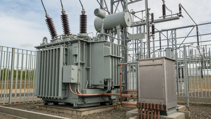
Key takeaways
- An earthing transformer provides an intentional neutral point for ungrounded or delta-connected systems to facilitate ground-fault protection and mitigate transient overvoltages.
- Zigzag (ZN) windings eliminate secondary back-feed risks and exhibit high positive-sequence impedance alongside low zero-sequence impedance without needing a tertiary winding.
- Continuous current ratings for grounding units are typically zero or low (auxiliary supply only), whereas short-time ratings must match system fault clear times—commonly 10 seconds under IEEE C57.32.
- Neutral grounding resistors connected to the neutral point limit earth-fault currents, typically to between 100 A and 1,000 A on medium-voltage distribution systems.
- Core zero-sequence impedance determines earth-fault magnitude and must be coordinated with upstream relaying to prevent thermal destruction during line-to-ground faults.
Quick answer: An earthing transformer is a specialised distribution transformer connected to an ungrounded or delta-connected three-phase system to derive an artificial neutral point for system earthing. This provides a low-impedance path for zero-sequence fault currents, enabling protective relays to rapidly detect and clear single line-to-ground faults while suppressing destructive transient overvoltages.
Delta-connected medium-voltage (MV) systems, commonly encountered in industrial complexes, offshore platforms, wind farms, and utility distribution networks operating at 11 kV, 22 kV, or 33 kV, possess no intrinsic neutral point. If an earth fault occurs on an isolated system, capacitive charging currents flow, causing dangerous voltage escalation up to 2.73 times the nominal line-to-neutral voltage due to intermittent arcing faults. Installing an earthing transformer—often called a neutral grounding transformer or neutral earthing transformer—stabilises line-to-ground voltages, limits equipment insulation stress, and ensures that sensitive directional ground-fault relays operate reliably in accordance with IEEE C57.32 and IEC 60076-6 clause 8.
Core Operating Principles of an Earthing Transformer
An earthing transformer functions by offering high impedance to balanced normal currents while presenting exceptionally low impedance to zero-sequence fault currents. Under balanced, steady-state conditions, line-to-neutral voltages across the three phases sum to zero. The core draws only a minimal magnetising current, resulting in negligible continuous losses. The unit sits virtually idle until insulation breakdown occurs on one of the phases.
When a single phase-to-earth fault develops, zero-sequence currents ($I_0$) divide equally among the three phases ($I_A = I_B = I_C = I_0$). In an interconnected winding, these currents produce equal magnetic fluxes that oppose each other in the core legs, effectively cancelling out. Consequently, the zero-sequence impedance ($Z_0$) of the transformer is governed solely by leakage reactance and winding resistance. This low zero-sequence impedance allows adequate current to circulate through an external neutral grounding resistor (NGR) or directly to earth, triggering trip thresholds on upstream circuit breakers.
Engineers integrating these units alongside equipment detailed in our transformer grounding system design guide must understand that earthing transformers are rated fundamentally differently from power transformers. While standard distribution units carry 100% rated load continuously, a neutral earthing transformer is typically designed for a continuous idling rating alongside a severe, short-time thermal rating—typically specified for 10 seconds, 30 seconds, or 60 seconds under fault conditions, as defined in IEEE C57.32 Table 1.
Zigzag (ZN) vs Star-Delta (YNd) Configurations
The two primary winding configurations used to establish a system neutral are the interconnected star (zigzag or ZN) and the wye-delta (YNd) arrangement. Selecting between these topologies depends on whether auxiliary low-voltage power is required alongside neutral provision, physical footprint constraints, and site-specific zero-sequence impedance targets.
The zigzag arrangement consists of six core coils across three legs, where each phase winding is split into two equal halves wound in opposition on different legs. For instance, phase A's winding shares core legs with phase B and phase C. This mechanical cross-connection guarantees that zero-sequence flux cancels within each leg, keeping zero-sequence reactance ($X_0$) low without generating circulating currents that could overheat secondary windings. Zigzag transformers are inherently compact, require no secondary terminations unless an auxiliary winding is added (ZNyn), and cannot propagate low-voltage phase faults back to the medium-voltage bus.
In contrast, the star-delta configuration uses a grounded wye primary winding paired with a closed delta secondary. Zero-sequence currents flowing into the grounded neutral induce circulating currents inside the closed delta winding, creating the required flux cancellation. If station auxiliary power is required, the delta winding can be sized to supply local loads (e.g., 400 V or 480 V low-voltage switchboards). However, any unbalanced single-phase load on the delta secondary manifests as zero-sequence heating on the primary, complicating relay coordination as discussed in our grounding transformer sizing guide.
| Design Parameter | Zigzag Connection (ZN / ZNyn) | Star-Delta Connection (YNd) |
|---|---|---|
| Footprint and Core Size | Standard (approx. 15% smaller core) | Larger (requires full delta rating) |
| Zero-Sequence Impedance ($Z_0$) | Engineered directly into winding geometry | Governed by primary-to-secondary leakage |
| Auxiliary LV Power Provision | Optional via separate low-capacity star winding | Inherent via closed delta secondary |
| Secondary Back-Feed Risk | Zero (no secondary winding required) | Moderate (delta faults reflect into MV neutral) |
| Thermal Overload Mechanism | Short-time zero-sequence heating only | Combined continuous load and fault heating |
| Typical Standards Compliance | IEC 60076-6, IEEE C57.32 | IEC 60076-1, IEEE C57.12.00 |
Sizing Calculations for a Neutral Grounding Transformer
Sizing a neutral grounding transformer requires calculating the short-time kVA capacity, zero-sequence impedance, and continuous thermal rating based on system line-to-line voltage and target ground-fault current. Consider a practical industrial facility operating at a nominal system voltage of $V_{LL} = 11\text{ kV}$ with an ungrounded delta feed, where the engineer specifies a maximum earth-fault current of $I_f = 400\text{ A}$ limited for a duration of $t = 10\text{ s}$.
- Calculate Phase-to-Neutral Voltage:
$V_{LN} = \frac{V_{LL}}{\sqrt{3}} = \frac{11,000\text{ V}}{1.732} = 6,351\text{ V}$ - Determine Required Total Neutral Resistance:
Assuming the neutral is grounded through a Neutral Grounding Resistor (NGR) and the transformer impedance is kept low (typically under 5% to 10% of total circuit impedance):
$R_N \approx \frac{V_{LN}}{I_f} = \frac{6,351\text{ V}}{400\text{ A}} = 15.88\text{ }\Omega$
The standard resistor rating is selected as $16\text{ }\Omega$, rated for $400\text{ A}$ at $10\text{ seconds}$. - Calculate Short-Time kVA Rating:
The short-time capacity ($kVA_{st}$) represents the apparent power handled during the fault window:
$kVA_{st} = \sqrt{3} \times V_{LL} \times I_0 = V_{LL} \times \frac{I_f}{\sqrt{3}} \times \sqrt{3} = V_{LN} \times I_f$
$kVA_{st} = 6.351\text{ kV} \times 400\text{ A} = 2,540.4\text{ kVA} \approx 2,541\text{ kVA}\text{ for } 10\text{ s}$ - Derive Equivalent Continuous kVA Rating:
Per IEEE C57.32 clause 6.3, standard short-time thermal multiplication factors permit translating short-time duration ratings to continuous thermal frame sizes. For a 10-second rating, the equivalent continuous frame factor is approximately 0.10 to 0.12 of the short-time kVA:
$kVA_{cont} \approx 2,541\text{ kVA} \times 0.105 = 266.8\text{ kVA}$
Consequently, a standard 315 kVA physical tank and core frame (oil-immersed transformer or cast-resin equivalent) will comfortably dissipate the thermal energy produced during a 10-second 400 A fault without exceeding the thermal limits set out in IEC 60076-2.
Protection Schemes for an Earthing Transformer
Protection of a neutral earthing transformer must account for both internal winding faults and thermal damage caused by prolonged external system ground faults. Because earthing transformers carry high currents exclusively during abnormal grid conditions, standard phase overcurrent curves alone do not provide adequate thermal protection.
As outlined in our guide on substation transformer protection engineering, protection schemes require a dedicated suite of relays:
- Neutral Overcurrent Relay (51N/51G): Connected to a current transformer (CT) placed on the neutral bushing lead running to the NGR. An inverse-time (IDMT) characteristic curve is coordinated to trip the transformer's MV circuit breaker before the NGR or winding exceeds its thermal time limit ($I^2t$).
- Instantaneous Ground Overcurrent (50N): Set above the maximum anticipated system charging current to clear high-magnitude internal faults within the transformer tank instantaneously.
- Restricted Earth Fault (REF / 87N): High-impedance or low-impedance REF relays compare the neutral lead current against the residual sum of the three phase CTs. This scheme detects inter-turn winding insulation failure close to the neutral point where standard overcurrent elements lack sensitivity.
- Thermal Replica Protection (49): Monitors accumulated heating during repetitive reclosing events. If line faults are cleared and re-energised repeatedly by auto-reclosers, thermal memory prevents coil burnout.
- Mechanical and Pressure Relief: Liquid-filled units must include a sudden pressure relay (63) and a dual-contact Buchholz relay to trip against arcing faults, coordinating with switchgear outlined in our substation protection and relay guide.
Installation, Site Testing, and Commissioning Checklist
Commissioning an earthing transformer demands rigorous verification of zero-sequence impedance, winding polarity, and neutral grounding continuity prior to MV energisation. Omission of zero-sequence impedance verification at site is a frequent cause of relay misoperation during initial fault clearance.
- Insulation Resistance and Polarisation Index: Measure HV-to-earth, LV-to-earth (if auxiliary winding exists), and HV-to-LV winding insulation using a 2.5 kV or 5 kV digital megohmmeter. Minimum acceptable insulation resistance at 20 degrees Celsius is 1,000 Megohms, with a Polarisation Index ($PI = R_{10min} / R_{1min}$) exceeding 2.0.
- Zero-Sequence Impedance Measurement ($Z_0$): Connect all three HV phase bushings together. Apply a single-phase AC test voltage between the shorted phase bushings and the neutral terminal. Measure applied voltage ($V_{test}$), total circulating current ($I_{test}$), and active power ($P_{test}$). Calculate zero-sequence impedance per phase as:
$Z_{0} = 3 \times \frac{V_{test}}{I_{test}}$
Verify that the calculated $Z_0$ matches the factory test certificate within the +/- 10% tolerance permitted by IEC 60076-1 clause 10. - Winding Resistance and Vector Group Verification: Measure DC winding resistance across all phase combinations using a Kelvin four-wire bridge. For zigzag units, verify phase symmetry to ensure balanced resistance across half-windings. Conduct a vector group test to confirm the 0-degree or 30-degree phase shift matches design documentation.
- Neutral Grounding Circuit Integrity: Perform continuity and resistance measurements from the neutral bushing through the disconnect link, current transformers, NGR elements, and the main substation ground grid. Ensure ground loop resistance complies with IEEE 80 touch-and-step voltage thresholds.
Next steps: specifying and sourcing
When specifying an earthing transformer for an upcoming project, supply the manufacturer with the exact system nominal and maximum voltage, rated short-time fault current and duration (e.g., 400 A for 10 s), desired zero-sequence impedance ($Z_0$), basic impulse level (BIL), and auxiliary winding kVA if local low-voltage power is needed. Explore our engineered power transformers, fluid-filled distribution equipment, and complete prefabricated transformer substations designed to meet IEC and IEEE utility criteria. For custom sizing assessments, quotation inquiries, and detailed vector diagrams, submit your project single-line diagram directly through our transformer quote portal or contact our application engineering team.
Frequently asked questions
What is the primary purpose of an earthing transformer?
An earthing transformer provides an artificial neutral point for delta-connected or ungrounded power systems. This neutral allows ground-fault current to return during phase-to-earth faults, enabling protective relays to clear faults while preventing dangerous transient overvoltages from damaging equipment insulation.
Why is a zigzag winding preferred for a neutral earthing transformer?
A zigzag winding splits each phase across two core legs in opposite directions, causing zero-sequence magnetic fluxes to cancel out. This design produces low zero-sequence impedance without needing a closed secondary delta winding, saving physical space and eliminating risks from secondary back-feed.
Can an earthing transformer supply auxiliary station power?
Yes, an earthing transformer can supply auxiliary power if configured with a secondary star winding (ZNyn connection) or when using a wye-delta (YNd) design. The auxiliary winding must be thermally sized for continuous low-voltage station loads in addition to fault-time duties.
How long must an earthing transformer withstand a ground fault?
Standard earthing transformers are rated to withstand ground faults for 10 seconds, 30 seconds, or 60 seconds, with 10 seconds being the standard default under IEEE C57.32. Upstream protection relays must disconnect the unit before these thermal limits are reached.
What is the difference between an earthing transformer and a power transformer?
A power transformer transfers energy continuously between different voltage levels under balanced load. An earthing transformer primarily carries zero current under normal conditions and is thermally rated for short-duration zero-sequence fault currents to establish a stable reference neutral.
Tags: earthing transformer neutral grounding transformer neutral earthing transformer transformer protection substation engineering


