Key takeaways
- A high voltage test validates the dielectric integrity of transformer insulation systems against transient overvoltages and steady-state operating stress.
- Separate-source AC withstand tests evaluate major insulation to earth and between windings, while induced overvoltage tests verify turn-to-turn and layer-to-layer minor insulation.
- Per IEC 60076-3 Table 1, equipment specified for a nominal 33 kV system typically undergoes a power-frequency withstand test at 70 kV RMS for 60 seconds.
- Test power requirements depend on winding capacitance, calculated as S = 2 * pi * f * C * V^2, requiring dedicated resonant test sets for large power apparatus.
- Partial discharge levels during induced testing must remain below 100 pC to 250 pC at 1.58 Um / sqrt(3) depending on the insulation medium and relevant IEC or IEEE standard.
Quick answer: A high voltage test is a mandatory dielectric verification procedure applied to electrical apparatus to confirm that insulation clearances and materials withstand specified power-frequency and transient overvoltages without breakdown or flashover. For transformers, this involves applied separate-source withstand tests and induced overvoltage tests conducted per IEC 60076-3 or IEEE C57.12.00.
Dielectric failure represents one of the primary causes of catastrophic asset loss in transmission and distribution networks. Factory acceptance testing (FAT) relies on rigorous dielectric verification before any equipment leaves the assembly floor. When commissioning or qualifying equipment, engineers must understand the specific stress mechanisms, setup requirements, and acceptance thresholds that distinguish minor insulation faults from robust, service-ready construction. For an overarching overview of routine and type verification stages, review our guide on how to test a transformer.
Core Methods in High Voltage Electrical Testing
High voltage electrical testing on transformers divides into tests that assess major insulation versus tests that verify minor insulation. Major insulation comprises the barriers, oil ducts, and structural standoffs separating the windings from the grounded core, tank, and adjacent phases. Minor insulation refers to the turn-to-turn enamels, paper wraps, and layer-to-layer insulating sheets within an individual winding.
Standard dielectric programmes employ two primary power-frequency methods: the separate-source AC withstand test (frequently called the applied potential test) and the induced overvoltage withstand test. While impulse tests simulate lightning strikes and switching surges using high-voltage waveforms (1.2/50 microseconds and 250/2500 microseconds respectively), power-frequency tests confirm continuous operational capability and resilience to short-duration system ground faults. Comprehensive evaluation also requires cross-referencing baseline metrics established during insulation testing procedures prior to energising high-potential equipment.
Applied Withstand vs Induced High Voltage Test
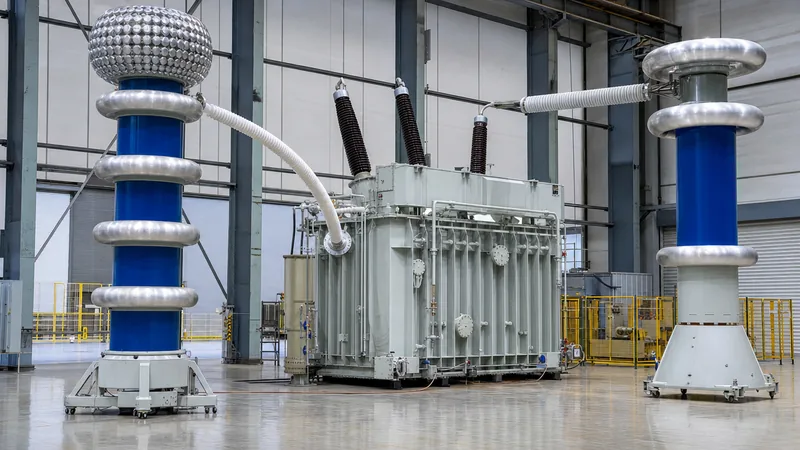
The applied withstand test and the induced overvoltage test deliver complementary electrical stress profiles across the internal insulating geometry. In an applied separate-source test, the manufacturer connects all terminals of the winding under test together, links all untested windings and the tank to earth, and applies an external high voltage from a test transformer for 60 seconds. This generates uniform potential across the entire winding, stressing only the insulation to earth and to neighbouring windings.
In contrast, an induced high voltage test energises the transformer from the low-voltage winding at an elevated voltage (typically 1.5 to 2.0 times rated voltage) while leaving the high-voltage winding open-circuited. Because applying double rated voltage at 50 Hz or 60 Hz would drive the magnetic core deep into saturation, the test generator must operate at an elevated frequency, usually 100 Hz to 400 Hz. The induced test creates a linear voltage gradient along the winding conductors, directly proving the integrity of inter-turn insulation, inter-disc spaces, and phase-to-phase clearances in three-phase units.
Standard Test Voltages: IEC 60076-3 and IEEE C57.12.00
Standard test levels depend on the highest voltage for equipment (Um) and whether the system operates with effective earthing. IEC 60076-3 clause 11 sets the power-frequency withstand voltages for standard distribution and power ratings, matching insulation coordinates to global grid conditions. IEEE C57.12.00 Table 5 provides analogous requirements for North American installations, specifying basic lightning impulse insulation levels (BIL) alongside applied potential targets.
| System Nominal Voltage (kV RMS) | Highest Voltage for Equipment Um (kV RMS) | IEC 60076-3 Power-Frequency Withstand (kV RMS, 1 min) | IEEE C57.12.00 Applied Potential (kV RMS, 1 min) | Standard Lightning Impulse Withstand (kV Peak) |
|---|---|---|---|---|
| 11 | 12 | 28 | 34 | 75 |
| 22 | 24 | 50 | 50 | 125 |
| 33 | 36 | 70 | 70 | 170 |
| 66 | 72.5 | 140 | 140 | 325 |
| 110 | 126 | 230 | 230 | 550 |
Specifying engineers must confirm whether uniform or non-uniform (graded) insulation applies. Star-connected windings with a permanently earthed neutral terminal frequently utilise graded insulation, allowing lower power-frequency withstand ratings near the neutral point, which reduces frame dimensions and physical weight on major sub-station units.
Step-by-Step Applied High Voltage Test Procedure
Conducting an applied high voltage test requires meticulous preparation to prevent catastrophic flashover and personnel hazard. The factory or field team must verify clearances, test connections, and environmental humidity before initiating voltage ramp-up.
- Isolate the unit completely, discharge residual static charges via grounded discharge rods, and confirm tank earth integrity.
- Short-circuit all terminals of the winding under test together using bare copper jumpers (e.g., tie 1U, 1V, 1W, and 1N into a single node).
- Short-circuit all terminals of other windings (such as 2U, 2V, 2W) and bond them directly to the main transformer tank ground point.
- Connect the high-voltage lead from the test set transformer to the jumpered bundle of the winding under test.
- Initialise voltage application at no more than 25% of the target test level, then raise the potential smoothly to 100% over a duration not exceeding 15 seconds.
- Hold the full test voltage steady for exactly 60 seconds while monitoring leakage current meters for trip events, abrupt rises, or audible discharges.
- Reduce the voltage steadily to below 25% of the target value over a span of 10 to 15 seconds, switch off the power supply, and ground the tested terminals to safely dissipate capacitive charge.
Executing these sequences demands calibrated transformer testing equipment, including voltage dividers, corona-free test leads, and protective current-limiting impedances.
Engineering Calculation: Test Set Sizing and Charging Current
A common pitfall during on-site high voltage electrical testing is underestimating the capacitive kVA demanded by the equipment under test. A transformer winding forms a distributed capacitor with respect to the core and tank. The test power supply must furnish sufficient reactive power to charge this capacitance at the test frequency, or the source will overload and drop output voltage.
Consider an applied test on the high-voltage winding of a 33 kV transformer, where the measured high-voltage to low-voltage plus ground capacitance (C_HL+E) equals 4.2 nanofarads (nF). The required applied test voltage according to IEC 60076-3 is 70 kV RMS at 50 Hz.
Calculate the capacitive reactance (X_c) of the winding system:
X_c = 1 / (2 * pi * f * C) = 1 / (2 * 3.14159 * 50 * 4.2 * 10^-9) = 757,880 ohms
Calculate the charging current (I_c) delivered by the high-voltage test set:
I_c = V_test / X_c = 70,000 V / 757,880 ohms = 0.0924 A (92.4 mA)
Calculate the minimum apparent power rating (S) required of the test transformer:
S = V_test * I_c = 70,000 V * 0.0924 A = 6.47 kVA
To avoid supply waveform distortion and thermal saturation, the test transformer should incorporate a continuous rating margin of at least 25%, indicating that a standard 10 kVA, 100 kV test transformer set is required for this specific asset.
Partial Discharge Integration During Dielectric Verification
While traditional pass-fail decisions during a high voltage test relied strictly on the absence of disruptive breakdown, modern quality standards demand concurrent partial discharge (PD) monitoring. Partial discharges are localised dielectric breakdowns of small gas voids, delaminations, or moisture pockets within the solid or liquid insulation system that do not bridge the entire space between conductors.
Per IEC 60076-3 clause 13, long-duration induced voltage testing (ACLD) evaluates PD over an extended cycle. The sequence elevates voltage to an inception level (typically 1.7 Um / sqrt(3)), holds for a brief screening window, drops to the continuous operating measurement level (1.58 Um / sqrt(3) or 1.3 Um / sqrt(3)), and logs discharge magnitude over 60 minutes. For oil-immersed units, stable background noise below 100 picoCoulombs (pC) with no persistent rising trend confirms sound insulation quality. For dry-type units evaluated per IEC 60076-11, PD must typically remain below 10 pC to verify resin penetration and void-free casting. To examine how full FAT programmes evaluate these parameters, consult our overview on power transformer testing.
Acceptance Criteria and Troubleshooting Test Failures
A high voltage test yields a passing result only when no dielectric collapse occurs, the test set trip circuit does not actuate, and current instruments display no sustained or step-like variations. An abrupt drop in test voltage accompanied by an overcurrent breaker trip indicates an insulation punch-through, a creepage track across a pressboard barrier, or an external bushing flashover.
When a dielectric test fails, engineers should execute a systematic fault isolation checklist:
- Inspect external surfaces: Clean all porcelain or composite bushings, as surface dirt, condensation, or grease can cause tracking that mimics internal structural faults.
- Isolate accessories: Disconnect surge arresters, capacitive voltage transformers (CVTs), and auxiliary monitoring probes that may possess lower withstand thresholds.
- Perform low-voltage diagnostic screening: Run insulation resistance and polarisation index (PI) checks, followed by winding power factor (tan delta) measurements to detect moisture penetration.
- Examine dissolved gas analysis (DGA): In liquid-filled units, run a DGA sample immediately following a breakdown to identify acetylene (C2H2) and hydrogen (H2), which indicate high-energy electrical arcing within the tank.
- Inspect core-ground leads: Verify that the internal core-to-ground grounding strap has not inadvertently disconnected or created multiple grounding paths.
Next steps: specifying and sourcing
Specifying dielectric requirements accurately ensures transformers arrive on site fully certified for system transients, switching surges, and environmental conditions. When requesting engineering bids, specify nominal grid voltage, maximum equipment voltage (Um), neutral grounding topology, required basic impulse level (BIL), and partial discharge limits. For utility networks, renewable parks, or industrial infrastructure, explore our power transformer solutions or our range of oil-immersed transformer and dry-type transformer units. Submit your single-line diagram and tender parameters directly to our technical team via our quote page for a tailored quotation.
Frequently asked questions
What is the purpose of a high voltage test on a transformer?
A high voltage test proves that the transformer insulation system withstands normal operating voltages and operational transients without dielectric breakdown. It verifies major insulation clearances to earth and minor insulation between individual winding turns.
What is the difference between an applied voltage test and an induced voltage test?
The applied voltage test uses an external power-frequency source on shorted windings to stress major insulation to earth for 60 seconds. The induced voltage test energises the winding at elevated frequency to stress inter-turn and inter-phase minor insulation along the winding path.
Why is high frequency used in an induced high voltage test?
Elevated test voltage at standard frequency would drive the transformer core into severe magnetic saturation, drawing excessive excitation current. Operating between 100 Hz and 400 Hz keeps magnetic flux density within permissible design limits during the overvoltage exposure.
What are the standard acceptance criteria for a transformer high voltage test?
The transformer must sustain the prescribed test voltage for the full 60-second period without insulation collapse, flashover, or overcurrent trip. Concurrent partial discharge testing must also demonstrate stable values below specified limits, typically under 100 pC to 250 pC.
How does moisture affect high voltage electrical testing results?
Moisture significantly degrades the dielectric strength of solid pressboard and transformer oil, lowering breakdown voltage. Wet insulation displays elevated dielectric loss factors (tan delta), increased leakage current, and early partial discharge inception during test sequences.
Can a high voltage test damage sound transformer insulation?
When performed according to standard voltages and durations specified in IEC 60076-3 or IEEE C57.12.00, a high voltage test does not degrade healthy insulation. However, repeated overpotential testing at 100% factory levels can cause cumulative electrical fatigue; repeat field tests are typically conducted at 75% to 80% of factory levels.
Tags: high voltage test high voltage electrical testing transformer testing dielectric withstand insulation testing


