Key takeaways
- Transformer testing equipment validates mechanical integrity, insulation dielectric health, and electromagnetic performance against IEC 60076 and IEEE C57 standards.
- Turns ratio testers must deliver ratio measurement accuracy within ±0.05% to detect inter-turn winding faults and incorrect tap-changer connections.
- Winding resistance meters utilise direct-current injection up to 50 A with rapid inductive discharge circuits to resolve resistance down to 0.1 micro-ohms.
- Dielectric dissipation factor and capacitance test sets operate at 10 kV to identify bulk moisture ingress and insulation degradation before thermal breakdown occurs.
- Specialised transformers for testing applications provide high-potential AC stresses up to hundreds of kilovolts with partial discharge levels below 2 picocoulombs.
Quick answer: Transformer testing equipment comprises specialised diagnostic instruments used to verify the electrical insulation, magnetic core integrity, winding ratios, and mechanical construction of transformers in accordance with international standards such as IEC 60076 and IEEE C57.12.90. These instruments enable electrical engineers to execute factory acceptance tests (FAT), pre-commissioning assessments, and preventative maintenance diagnostics.
Ensuring grid reliability requires rigorous electrical verification at every stage of an asset's lifecycle. Selecting the appropriate transformer testing equipment is critical for identifying nascent defects, such as winding deformation, partial discharge (PD), moisture saturation in solid insulation, and contact degradation in on-load tap changers (OLTC). Whether performing standard factory acceptance checks on a high-voltage power transformer or conducting predictive substation maintenance, deploying accurate, calibrated test instruments mitigates catastrophic field failures. For a broader overview of testing methodologies, consult our comprehensive guide on how to test a transformer.
Essential Power Transformer Testing Equipment and Diagnostic Tools
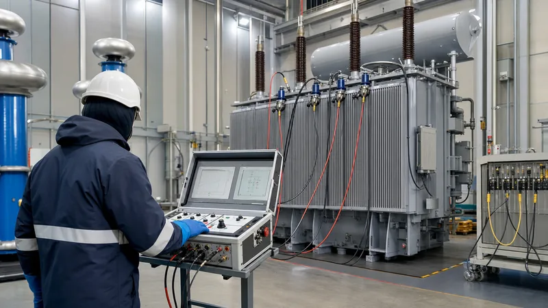
Essential power transformer testing equipment comprises dedicated instruments designed to assess dielectric properties, electromagnetic circuit continuity, and mechanical winding geometry under field and laboratory conditions. In modern substations, testing engineers rely on portable yet laboratory-grade instruments capable of overcoming severe electromagnetic interference (EMI) typical of live switchyards.
The foundational suite of power transformer testing equipment includes:
- Transformer Turns Ratio (TTR) Testers: High-precision digital instruments that apply single-phase or three-phase low excitation voltages (typically 8 V to 250 V AC at 50/60 Hz) to verify the primary-to-secondary turns ratio across all tap positions, confirming phase displacement vectors (e.g., Dyn11, YNd1) and detecting shorted turns.
- Winding Resistance Ohmmeters: High-current direct-current (DC) sources delivering 10 A to 50 A to measure low-ohmic winding resistance, detect loose bolted connections, and evaluate tap-changer contact wear. Modern units incorporate dual-channel reading and dual-core demagnetisation circuitry to neutralise residual core flux before returning the unit to service.
- Insulation Resistance (IR) and Polarisation Index (PI) Meters: Battery- or mains-powered testers delivering regulated test voltages up to 5 kV or 10 kV DC to evaluate bulk insulation integrity between individual windings and ground. Detailed evaluation metrics are detailed in our guide on insulation testing procedures and standards.
- Capacitance and Tan Delta (δ) Test Sets: High-voltage AC dielectric bridge sets (typically energised at 10 kV, 45–65 Hz variable frequency) that evaluate the loss angle (dissipation factor) of bushing grading layers and bulk paper-oil insulation barriers.
- Sweep Frequency Response Analysers (SFRA): Low-voltage RF signal generators (measuring transfer functions from 10 Hz to 20 MHz per IEC 60076-18) that identify internal core shifts, radial winding hoop buckling, and axial winding displacement following short-circuit fault events or transit shocks.
Key Test Instruments, Parameters, and Applicable Standards
Every testing instrument must adhere to strict metrological standards to ensure repeatable and actionable diagnostic data across routine, type, and special testing regimes. Selecting calibrated instruments guarantees that measurements comply with limits defined by international governing bodies such as the International Electrotechnical Commission (IEC) and the Institute of Electrical and Electronics Engineers (IEEE).
The following table outlines the primary testing equipment categories, their measurable parameters, standard test levels, and associated reference standards:
| Test Instrument | Primary Parameter Measured | Standard Excitation Level | Measurement Range & Accuracy | Governing Standard |
|---|---|---|---|---|
| Turns Ratio Tester (TTR) | Voltage ratio, phase angle error | 8 V – 250 V AC, 50/60 Hz | 0.8 to 50,000 ratio (±0.05% accuracy) | IEC 60076-1, IEEE C57.12.90 |
| Winding Resistance Meter | DC winding resistance, OLTC dynamic continuity | 10 A – 50 A DC constant current | 0.1 μΩ to 2 kΩ (±0.25% accuracy) | IEC 60076-1, IEEE C57.12.90 |
| 10 kV Tan Delta Set | Dissipation factor (tan δ), power factor (cos φ), capacitance | 200 V – 12 kV AC, variable 45–65 Hz | Cap: 10 pF to 2.5 μF; Tan δ: 0 to 100% (±0.01% resolution) | IEEE C57.12.90, IEC 60076-3 |
| Insulation Resistance Tester | Megaohm resistance, Polarisation Index (10 min / 1 min), Dielectric Absorption Ratio | 500 V, 1 kV, 2.5 kV, 5 kV, 10 kV DC | 10 kΩ to 30 TΩ (±5% up to 1 TΩ) | IEEE 43, IEC 60076-1 |
| SFRA Test Set | Transfer function response (dB magnitude, phase angle) | 10 V peak-to-peak into 50 Ω termination | 10 Hz to 20 MHz (>100 dB dynamic range) | IEC 60076-18, IEEE C57.149 |
| Oil Dielectric Breakdown Tester | Dielectric breakdown voltage of insulating liquid | 0 to 80 kV or 100 kV AC (2.0 kV/s rise rate) | 0.1 kV resolution (±1% accuracy) | IEC 60156, ASTM D877, ASTM D1816 |
For liquid-immersed transformers, dielectric fluid parameters are equally critical; comprehensive fluid verification methods are detailed in our engineering overview of transformer oil testing standards.
Step-by-Step Commissioning Routine Using Transformer Testers
A commissioning testing routine requires a disciplined sequence of measurements to prevent instrument damage, minimise test lead reconnections, and ensure total de-energisation between high-voltage stress cycles. Field engineers must verify that all transformer testers are grounded to a common low-impedance substation ground bus before attaching test leads.
- Perform Visual, Mechanical, and Grounding Verification: Verify the primary and secondary neutral grounding connections, verify core-to-ground and core-clamp ground insulation, inspect bushing ceramic surfaces for micro-fissures, and confirm oil levels on main conservators and OLTC compartments of an oil-immersed transformer.
- Conduct Sweep Frequency Response Analysis (SFRA): Measure the baseline fingerprint across all phase windings before applying any DC currents. Applying DC resistance testing first can leave remnant core magnetism that skews sub-kilohertz SFRA frequency curves.
- Execute Turns Ratio and Vector Group Verification: Connect the three-phase TTR test leads to high-voltage and low-voltage terminals. Cycle the tap changer through every physical position (e.g., tap 1 through tap 17 or 33), recording the exact voltage ratio and phase deviation; verify that measured ratios match factory test report nameplate values within ±0.5%.
- Perform Winding Resistance and Dynamic Tap-Changer Testing: Inject regulated DC across high-voltage and low-voltage windings. Record stable resistance readings normalised to 75°C or 85°C. Transition the on-load tap changer across all steps under active measurement to confirm unbroken contact transition (dynamic resistance measurement), detecting worn diverter switch contacts or bounce.
- Demagnetise the Core: Engage the demagnetisation function on the winding ohmmeter to cycle alternating polarities of decaying direct current through the magnetic core, eliminating remanence that causes high inrush currents upon energisation.
- Measure Dielectric Dissipation Factor and Capacitance: Apply 10 kV AC across winding-to-winding and winding-to-tank insulation systems using UST (Ungrounded Specimen Test) and GST (Grounded Specimen Test) guard modes. Confirm that the power factor remains below 0.5% for modern mineral oil-filled units at 20°C reference temperature.
- Complete High-Voltage DC Insulation Resistance Tests: Apply 5 kV or 10 kV DC between windings and ground for 10 minutes, logging readings at 15 seconds, 60 seconds, and 600 seconds to compute the Dielectric Absorption Ratio (DAR = R60s / R15s) and Polarisation Index (PI = R10min / R1min, target > 2.0).
Transformers for Testing Applications and High-Voltage Test Bays
Transformers for testing applications are custom-engineered electromagnetic systems constructed specifically to supply extreme voltages or heavy currents within manufacturing test bays and accredited high-voltage research laboratories. Unlike conventional power distribution units designed for continuous load delivery, transformers for testing applications are built for cyclic duty, low internal impedance, and exceptional dielectric endurance.
Key topologies include:
- Cascaded AC High-Potential Test Transformers: Multi-stage units connected in series cascade (insulated from ground on insulating cylinders) designed to produce AC voltages exceeding 500 kV to 1,200 kV RMS for applied high-voltage withstand testing of insulation barriers per IEC 60076-3.
- Resonant Test Systems (Variable Inductance or Variable Frequency): High-voltage reactor and exciter transformer combinations designed to form a series-resonant circuit with the capacitive load of the transformer under test. This allows high-voltage energisation with minimal active power consumption from the factory utility supply.
- Ultra-Low Partial Discharge (PD) Testing Transformers: Precision-wound transformers incorporating multi-layer electrostatic screening to guarantee background PD levels below 1 picocoulomb (pC) at 120% nominal test voltage, preventing false PD readings during induced overvoltage testing with PD measurement (IVPD).
- High-Current Injection Transformers: Low-voltage, high-amperage transformers capable of driving currents from 1,000 A to 100,000 A for temperature-rise (heat run) heat-soak tests and short-circuit withstand dynamic tests.
These specialised test transformers require custom core geometry and high thermal capacity to handle the short-duration, high-stress conditions encountered during factory type testing of medium-voltage units, including a cast-resin dry-type transformer.
Best Practices for Field Diagnostics and FAT Interpretation
Accurate interpretation of test results requires correcting field-acquired raw values to reference temperatures and maintaining rigorous safety protocols to prevent arc-flash and electrical shock hazards. Because ambient site conditions fluctuate widely, raw insulation resistance and dissipation factor measurements cannot be evaluated without temperature normalisation.
When reviewing field diagnostics against factory acceptance test (FAT) documentation, engineers should apply the following guidelines:
- Apply Temperature Correction Factors: Insulation resistance doubles for roughly every 10°C drop in winding temperature, whereas tan delta increases with rising temperatures. Always normalise dissipation factor and insulation resistance readings to 20°C using standard conversion curves (e.g., IEEE C57.12.90 Annex) to avoid misdiagnosing healthy insulation as degraded.
- Ensure Ground Isolation on Bushing Test Taps: Bushing C1 (core conductor to tap) and C2 (tap to ground flange) capacitance and dissipation factor tests require clean, completely dry test tap insulator bodies. A contaminated tap surface introduces parallel leakage paths that lead to elevated dielectric loss readings.
- Verify Demagnetisation Prior to Energisation: Residual magnetic flux left in the core after DC winding resistance testing can cause inrush currents up to 8–10 times the rated full-load current during initial system energisation, potentially tripping differential relays and causing mechanical stress on winding coils.
- Cross-Reference Multiple Diagnostic Modalities: Never condemn an asset based on a single parameter. An elevated winding resistance reading should be cross-verified against turns ratio phase displacement and tap-changer dynamic torque/current signatures before initiating an internal tank inspection.
Next steps: specifying and sourcing
When specifying custom distribution or power transformers, defining factory acceptance test protocols and requiring baseline diagnostic test sheets is critical for long-term fleet management. Project engineers should include detailed testing standards (IEC 60076, IEEE C57, or equivalent) in their technical procurement specifications to guarantee baseline SFRA signatures, dielectric loss reports, and certified turns ratio logs upon delivery.
Explore our complete range of certified power transformers, distribution units, and skid-mounted substations engineered to international standards. For bespoke engineering inquiries or to submit project specifications for a tailored quotation, contact our technical sales team via our quotation portal or reach out directly through our contact page.
Frequently asked questions
What is the most critical transformer testing equipment for field commissioning?
The transformer turns ratio (TTR) tester and the insulation resistance (IR) tester are the most critical tools for initial commissioning. Together, they verify winding polarity, vector grouping, turn-to-turn insulation, and bulk electrical isolation between phases and ground before energisation.
Why is SFRA testing conducted before winding resistance testing?
Sweep frequency response analysis (SFRA) must be conducted before winding resistance testing because DC injection leaves residual magnetic flux in the core. Residual remanence significantly shifts the low-frequency response (below 1 kHz), distorting the mechanical baseline curve and yielding false indicators of core movement.
How does power transformer testing equipment measure dynamic OLTC resistance?
Dynamic OLTC resistance testers inject a constant DC current through the tap selector contacts while recording high-speed current and ripple voltage transients during the mechanical tap transition. Any momentary contact open-circuit or bouncing transition appears as an abrupt current drop on the measurement graph.
What is an acceptable Tan Delta value for new power transformers?
According to IEEE C57.12.90, an acceptable dissipation factor (Tan Delta) for new oil-immersed power transformers at 20°C reference temperature is 0.5% or lower. Values between 0.5% and 1.0% warrant close investigation, while values exceeding 1.0% indicate severe moisture or insulation degradation.
What are transformers for testing applications used for?
Transformers for testing applications are specialised high-voltage or high-current units used in laboratories to perform dielectric withstand, induced overvoltage, partial discharge, and temperature-rise testing. They feature low background noise (often below 2 pC) and high transient withstand capabilities.
Can winding resistance meters be used to test dry-type transformers?
Yes, high-precision DC winding resistance meters are routinely used on dry-type transformers to verify terminal joint torques and winding balance. However, lower test current settings (typically 10 A or less) are recommended to prevent excessive I2R heating of small conductor cross-sections.
Tags: transformer testing equipment power transformer testing equipment transformer testers transformers for testing applications transformer diagnostics


