Key takeaways
- Transformers are rated in apparent power (volt-amperes, kVA, or MVA) rather than active power (kW) because internal losses and thermal limits depend strictly on voltage and current, independent of load power factor.
- A transformer rating represents the continuous apparent power the unit can deliver at rated secondary voltage and frequency without exceeding winding temperature rise limits specified by IEC 60076 or IEEE C57.12.00.
- Three-phase transformer capacity is calculated using the formula S = sqrt(3) x V x I, where S is apparent power in volt-amperes, V is line-to-line voltage in volts, and I is rated line current in amperes.
- Cooling methods dynamically alter capacity, allowing dual- or triple-rated units (such as ONAN/ONAF) to deliver 25% to 33% higher output when forced cooling fans or pumps are activated.
- Operating non-linear loads with high harmonic content generates supplementary eddy-current losses, necessitating K-factor de-rating in accordance with IEEE C57.110 standards.
Quick answer: Transformers are rated in apparent power—specifically volt-amperes (VA), kilovolt-amperes (kVA), or megavolt-amperes (MVA)—which defines the maximum continuous product of rated voltage and current the unit can deliver without exceeding standardized winding temperature limits. This thermal rating remains valid regardless of the load power factor connected to the secondary terminals.
Understanding how are transformers rated is fundamental to designing robust electrical networks for industrial plants, utilities, and commercial facilities. When electrical engineers select equipment, they must decipher nameplate parameters governed by standards such as IEC 60076 and IEEE C57.12.00. Because core excitation losses depend on operating voltage while copper winding losses depend on current magnitude, equipment capacity is inherently decoupled from the real work (kilowatts) performed by the load. Sizing equipment accurately prevents catastrophic dielectric breakdown and premature insulation ageing, ensuring capital expenditure aligns precisely with operational demand.
Why Transformers Are Rated in kVA Instead of kW
Transformers are rated in apparent power because internal heat generation is determined strictly by system voltage and load current, irrespective of the phase angle between them. In electrical engineering, transformers are usually rated in units called volt-amperes (VA), kilovolt-amperes (kVA), or megavolt-amperes (MVA).
Total transformer losses comprise two distinct physical phenomena: core losses (iron losses) and winding losses (copper or $I^2R$ losses). Core losses consist of hysteresis and eddy current dissipation within the magnetic core laminations. These losses depend almost entirely on the primary voltage magnitude and frequency, governed by the peak magnetic flux density ($B_{max}$). Conversely, winding losses are purely a function of the square of the load current ($I$) conducted through the primary and secondary conductor resistances ($R$).
Because active power ($P$, measured in kW) equals $V \times I \times \cos\theta$, a load operating at a poor power factor ($ ext{PF} = \cos\theta$) draws significantly more current for the same kilowatt output. If a transformer were rated in kW, a customer connecting a 1,000 kW load at a 0.5 lagging power factor would draw 2,000 kVA of current. This excessive current would produce four times the nominal $I^2R$ heating in the windings, destroying the solid insulation even though the kW threshold was not breached. For a comprehensive sizing methodology that incorporates power factor and motor starting parameters, consult our Transformer Sizing Calculator Guide.
Thermal Limits and Temperature Rise Standards
A transformer rating is fundamentally a thermal limit defined by how hot the internal components can safely operate over a projected 20- to 30-year operational lifespan. International standards classify transformer performance around specific maximum ambient temperatures and permissible temperature rise limits above ambient.
Under IEC 60076-2, standard ambient conditions assume an annual average temperature not exceeding 20 °C, a monthly average of 30 °C during the hottest month, and a maximum ambient peak of 40 °C. For standard mineral-oil-immersed units with Class A insulation (thermal index 105 °C), the standard limits the average winding temperature rise to 65 K (measured by resistance) and the top-oil temperature rise to 60 K. The hottest-spot winding temperature must not exceed 98 °C under continuous rated load to maintain a relative rate of thermal ageing equal to 1.0.
In North American practice governed by IEEE C57.12.00, standard ratings specify a 65 °C average winding temperature rise over a 30 °C average (40 °C maximum) ambient, allowing a maximum hot-spot rise of 80 °C (resulting in a 110 °C absolute hot spot). For dry-type transformers, insulation systems routinely utilize Class 155 (F), Class 180 (H), or Class 220 (C) materials, tolerating average winding rises of 80 °C, 115 °C, or 150 °C respectively. Exceeding these thermal limits halves insulation life for every 6 °C to 8 °C increment above the allowable hot-spot temperature.
How Transformer Rating Is Calculated: Mathematical Formulas
Calculating a transformer rating requires establishing the relationship between system phase configuration, rated operational voltage, and full-load line current. The primary formula for three-phase systems is:
$$S = \sqrt{3} \times V_{LL} \times I_L$$
Where:
- $S$ is apparent power expressed in volt-amperes (VA). Divide by 1,000 for kVA, or 1,000,000 for MVA.
- $V_{LL}$ is the nominal line-to-line voltage in volts (V).
- $I_L$ is the rated line current in amperes (A).
For single-phase installations, the factor $\sqrt{3}$ is omitted, simplifying the calculation to $S = V \times I$. When designing substation switchgear, protection engineers invert this formula to calculate rated full-load current ($I_{FLC}$), which dictates protective device thresholds. For guidance on sizing upstream breakers based on full-load amps, see our detailed Transformer Breaker Size Chart.
Worked Engineering Example: Consider a three-phase distribution unit stepping down an 11 kV grid voltage to 415 V line-to-line. If the required secondary full-load current is 1,391 A, the required apparent power rating is calculated as:
$$S = 1.73205 \times 415\text{ V} \times 1391.2\text{ A} = 999,997\text{ VA} \approx 1,000\text{ kVA}$$
The unit must therefore carry a nominal continuous rating of 1,000 kVA. If the connected industrial load draws 800 kW at a lagging power factor of 0.80, the load requires exactly $800 / 0.80 = 1,000\text{ kVA}$, loading the transformer to 100% of its thermal rating.
Cooling Classes and Multi-Stage Ratings
Cooling mechanisms directly dictate how are transformers rated under varying operational loads by augmenting the rate of heat extraction from the active core and windings. Medium and large power transformers frequently exhibit multi-stage ratings on their nameplates, represented by slash-delimited numbers such as 15/20/25 MVA or 1000/1333 kVA.
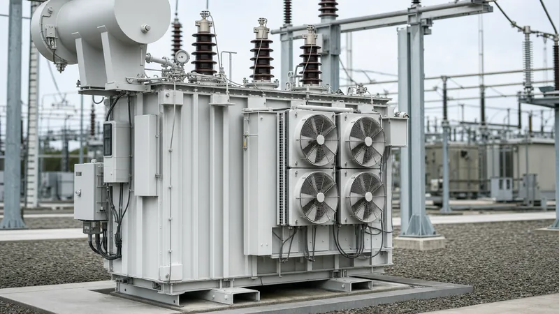
Under both IEC 60076-2 and IEEE C57.12.00, standardized letter designations define internal and external cooling mediums alongside circulation modes. In an ONAN (Oil Natural Air Natural) design, circulating mineral oil transfers heat to external radiator tubes via thermosiphon action, which dissipates into ambient air by natural convection. Adding external electric fans changes the designation to ONAF (Oil Natural Air Forced), increasing the continuous heat dissipation capacity and raising the allowable transformer rating by 25% to 33% without exceeding winding hot-spot limits.
The table below summarizes standard cooling classes and their typical capacity enhancement factors over baseline natural convection:
| Cooling Designation (IEC) | IEEE Designation | Internal Cooling Medium | External Cooling Medium | Typical Rating Increase Over Baseline |
|---|---|---|---|---|
| ONAN | OA | Mineral oil, natural convection | Air, natural convection | Baseline (100% capacity) |
| ONAF | FA | Mineral oil, natural convection | Air, forced circulation (fans) | +25% to +33% |
| OFAF | FOA | Mineral oil, forced circulation (pumps) | Air, forced circulation (fans) | +50% to +66% |
| OFWF | FOW | Mineral oil, forced circulation (pumps) | Water, forced circulation (heat exchanger) | +60% to +75% |
| AN / AF | AA / FA | Air, natural convection (dry-type) | Air, forced circulation (blowers) | +33% to +50% |
Short-circuit withstand performance and internal voltage regulation change across cooling stages because the percent impedance remains fixed to the core-winding geometry, while base current increases. Engineers must model fault levels using proper per-unit bases, as explored in our technical overview of Transformer Impedance Calculations.
Harmonics, K-Factor, and De-Rating Considerations
Non-linear electronic loads invalidate conventional nameplate ratings by injecting harmonic currents that cause severe supplementary heating in transformer windings. In modern facilities containing variable frequency drives (VFDs), uninterruptible power supplies (UPS), and solar inverters, standard equipment must be intentionally de-rated or specified with a high K-factor rating.
Harmonic currents increase transformer losses in two ways: by increasing high-frequency eddy current losses in the copper conductors, which scale approximately with the square of the harmonic frequency ($f_h^2$), and by elevating stray flux losses in structural steel clamps and tank walls. Standard transformers manufactured strictly to IEC 60076 are designed for purely sinusoidal currents with a Total Harmonic Distortion (THD) below 5%. When THD exceeds this limit, continuous capacity must be de-rated in accordance with IEEE C57.110.
The K-factor represents a weighted multiplier evaluating harmonic severity:
$$K = \sum_{h=1}^{h_{max}} I_h^2 \times h^2$$
Where $h$ is the harmonic order and $I_h$ is the per-unit current at that harmonic. A standard distribution transformer corresponds to $K=1$. Commercial and industrial installations commonly mandate $K=4$, $K=13$, or $K=20$ ratings, requiring transposed windings, paralleled smaller conductor strips to limit skin effect, and doubled neutral conductor cross-sections.
How to Read a Transformer Nameplate Rating
A transformer rating plate provides the verified design boundaries established during factory acceptance testing (FAT). To properly interpret nameplate parameters, follow this sequential engineering procedure:
- Identify the Rated Apparent Power (kVA/MVA): Locate the rated power entries. If multi-stage cooling is present, note both the base rating (e.g., ONAN) and the auxiliary forced-cooled rating (e.g., ONAF).
- Verify Primary and Secondary Rated Voltages: Check the nominal line-to-line voltages (e.g., 11,000 V to 415 V) and phase connection symbology (such as Dyn11, indicating a delta-connected high-voltage winding and a star-connected low-voltage winding with a 30-degree phase lead).
- Read the Rated Currents: Identify the line currents corresponding to each voltage and cooling stage. These values establish the upper threshold for protective relay pickups and thermal overload curves.
- Examine Percent Impedance (%Z): Note the measured short-circuit impedance at reference temperature (typically 75 °C or 115 °C). This figure dictates fault level contribution and busbar voltage drop under varying power factors.
- Check the Insulation Class and Temperature Rise: Verify that the specified winding rise (e.g., 65 °C rise over 40 °C ambient) matches site environmental conditions and altitude constraints (installations above 1,000 metres require de-rating due to reduced air density).
Next steps: specifying and sourcing
Selecting the optimal transformer rating requires balancing present steady-state loads, projected facility expansion, ambient thermal profiles, and harmonic load content. When requesting a proposal, prepare single-line diagrams detailing primary/secondary voltages, required basic impulse insulation level (BIL), tapping ranges, site altitude, and short-circuit levels.
Our engineering team designs and manufactures utility-grade oil-immersed transformers, high-efficiency dry-type transformers, and substation-class power transformers fully compliant with IEC 60076, IEEE C57, and regional efficiency regulations. For custom sizing assessments, tender specifications, or competitive pricing, submit your project schedule to our engineering sales division through our transformer quotation page.
Frequently asked questions
how are transformers rated
Transformers are rated in apparent power (kVA or MVA), which represents the product of rated line voltage and rated full-load current. This rating defines the continuous thermal capacity the unit can handle without exceeding standardized winding insulation temperature limits, independent of load power factor.
Why are transformers rated in kVA instead of kW?
Transformers are rated in kVA because iron core losses depend entirely on operating voltage and copper losses depend on load current. Since the manufacturer cannot predict the power factor of connected loads, rating the unit in active power (kW) could cause excessive current and severe thermal overload.
What does a 500 kVA transformer rating mean?
A 500 kVA transformer rating means the equipment can continuously deliver 500 kilovolt-amperes of apparent power under rated voltage, frequency, and standard ambient conditions. If operating a purely resistive load (1.0 power factor), it delivers 500 kW; at a 0.8 power factor, it safely supports 400 kW.
How does temperature rise affect transformer rating?
Temperature rise directly sets the maximum continuous kVA output by limiting internal conductor heat to prevent insulation degradation. Operating in ambient temperatures higher than 40 °C or exceeding standard winding temperature rises (such as 65 K for oil-filled units) accelerates paper ageing and mandates output de-rating.
What is the difference between ONAN and ONAF ratings?
The difference between ONAN and ONAF ratings reflects the increase in capacity gained by switching from natural convection cooling to forced-fan cooling. Activating external fans on radiators extracts heat faster, typically allowing the transformer to deliver 25% to 33% more kVA without exceeding safe internal temperatures.
How do non-linear loads affect transformer ratings?
Non-linear loads generate harmonic currents that dramatically increase eddy current and stray flux losses, overheating the winding copper and core clamps. Standard units must either be de-rated according to IEEE C57.110 calculations or replaced with transformers engineered with a specific K-factor rating (e.g., K-13).
Tags: how are transformers rated transformer rating transformers are usually rated in units called kVA rating IEC 60076


