Key takeaways
- Wiring a transformer requires verifying primary and secondary nameplate voltages, polarity marks, and phase displacement before making terminations.
- Single-phase transformers can be wired in series for higher voltage or in parallel for higher current, provided primary and secondary polarity markings align strictly.
- Three-phase connections must follow defined vector groups such as Dyn11 or YNd1 to prevent circulating currents and phase-shift mismatches.
- All electrical terminations require calibrated torque tightening per manufacturer specifications to prevent thermal runaway and hot spots under continuous load.
- Post-wiring verification requires insulation resistance and turns ratio testing per IEEE C57.12.90 or IEC 60076-1 prior to initial energisation.
Quick answer: To wire up a transformer, de-energise and lock out source feeders, confirm terminal markings (primary H-terminals, secondary X-terminals), match the system phase rotation or single-phase polarity, connect conductors to calibrated torque specifications, and bond the neutral and tank ground per local electrical codes. Pre-commissioning verification with insulation resistance and voltage-ratio tests is mandatory before applying line voltage.
Understanding how to wire up transformer equipment correctly is fundamental to electrical safety, equipment longevity, and system reliability. Whether installing a low-voltage dry-type unit in a commercial facility or commissioning an outdoor medium-voltage unit substation, termination errors account for a significant portion of early operational failures. Incorrect phase angles, improperly bonded grounding conductors, and loose lug torque create fire hazards, circulating harmonic currents, and catastrophic insulation breakdown. This technical guide outlines the engineering principles, standard terminal designations, step-by-step execution procedures, and validation checklists required to wire up distribution and power transformers safely.
Terminal Designations and Nameplate Interpretation
Terminal designations identify the voltage level, phase sequence, and winding polarity required to connect a transformer safely. Under IEC 60076-1 and IEEE C57.12.00, primary high-voltage terminals are designated by 1U, 1V, 1W (IEC) or H1, H2, H3 (IEEE), while low-voltage secondary terminals are designated by 2U, 2V, 2W, 2N (IEC) or X1, X2, X3, X0 (IEEE). Single-phase dual-voltage transformers commonly feature four secondary studs (X1, X2, X3, X4) that enable series or parallel secondary arrangements depending on whether the system requires 120/240 V split-phase or 120 V single-voltage service.
Before stripping conductors, engineers must inspect the transformer nameplate diagram. The nameplate specifies rated kVA, primary and secondary rated voltages, rated line currents, connection diagrams, tap changer configurations, and the vector group. Understanding rated load current is critical for sizing terminal cables; engineers can verify current calculations using our transformer current calculation formulas guide. If secondary tap jumpers or internal links must be adjusted for local line voltages, set them prior to pulling feed cables into the terminal enclosure.
How to Wire up Transformer in Single-Phase Configurations
Wiring a single-phase transformer requires matching source voltage to primary bushings and configuring secondary windings in series or parallel. Single-phase dry-type or pole-mounted units often provide dual primary coils (such as 240/480 V) and dual secondary coils (such as 120/240 V). Connecting coils in series doubles the voltage rating at rated coil current, whereas connecting them in parallel doubles the current capacity at the base coil voltage. Reviewing the single phase transformer guide helps clarify internal winding geometry before landing leads.
The table below details standard connection configurations for dual-winding single-phase transformers using IEEE terminal nomenclature:
| Configuration Type | Primary Terminals (Line In) | Primary Jumpers | Secondary Terminals (Load Out) | Secondary Jumpers | Output Voltage / Application |
|---|---|---|---|---|---|
| Series Primary / Series Secondary | H1, H4 | H2 to H3 | X1, X4 (centre tap = Neutral) | X2 to X3 | 480 V in to 120/240 V 3-wire split-phase |
| Series Primary / Parallel Secondary | H1, H4 | H2 to H3 | X1, X4 | X1 to X3, X2 to X4 | 480 V in to 120 V 2-wire high-current |
| Parallel Primary / Series Secondary | H1, H4 | H1 to H3, H2 to H4 | X1, X4 (centre tap = Neutral) | X2 to X3 | 240 V in to 120/240 V 3-wire split-phase |
| Parallel Primary / Parallel Secondary | H1, H4 | H1 to H3, H2 to H4 | X1, X4 | X1 to X3, X2 to X4 | 240 V in to 120 V 2-wire maximum amperage |
When wiring a 3-wire split-phase secondary (120/240 V), the series junction between X2 and X3 serves as the neutral conductor. In accordance with NEC Article 250.30 or IEC 60364-5-54, this centre point must connect directly to the system grounding electrode conductor and the enclosure ground bus to establish a solidly grounded secondary reference.
How to Connect Transformer in Three-Phase Vector Groups
To connect a three-phase transformer, match system phase conductors to designated high-voltage bushings and verify the vector group displacement angle before landing secondary cables. Three-phase distribution units frequently employ Delta-Wye configurations, such as Dyn11 (IEC) or standard 30-degree electrical lag (IEEE). In a Dyn11 configuration, the primary winding is connected in Delta with high-voltage lines feeding H1, H2, and H3 (or 1U, 1V, 1W), while the secondary winding forms a Wye with neutral point X0 (2N) grounded, providing a 30-degree secondary phase lead relative to the primary.
Proper feeder routing depends directly on the distribution scheme, such as whether the installation uses a loop or radial feed. Facility designers evaluate these topologies in our radial feed vs loop feed guide. For standard Delta-Wye systems, execute the three-phase connection using these guidelines:
- Primary Delta connection: Land incoming medium-voltage or low-voltage supply cables onto terminals H1 (Phase A), H2 (Phase B), and H3 (Phase C). Ensure appropriate electrical clearance between bare live parts and earthed metal walls in accordance with IEC 60076-3 minimum air clearances.
- Secondary Wye connection: Connect outgoing phase loads to X1 (Phase A), X2 (Phase B), and X3 (Phase C). Route the system neutral conductor from the insulated X0 bushing directly to the main low-voltage switchboard neutral bar.
- Bonding jumper installation: If the unit functions as a separately derived system, install a main bonding jumper between the neutral terminal X0 and the equipment grounding terminal within the transformer enclosure or first disconnecting switchboard per NEC Article 250.28.
Step-by-Step Procedure to Wire up a Distribution Transformer
Wiring up a transformer systematically minimises physical strain on bushings and prevents costly commissioning errors. Follow this step-by-step field procedure on de-energised, isolated equipment:
- Isolate, lock out, and ground: De-energise all upstream and downstream supply sources. Apply Lockout/Tagout (LOTO) padlocks, verify zero energy with an appropriately rated, calibrated contact voltage detector, and apply personal safety earths on both sides.
- Inspect and clean the cabinet: Remove shipping covers, check internal compartments for foreign objects, debris, or moisture ingress, and verify that the core and coil assembly has sustained no transit damage.
- Set tap changer positions: Confirm that the off-circuit tap changer (OCTC) switch or de-energised link board matches the intended nominal incoming line voltage before terminating cables.
- Pull and dress incoming/outgoing cables: Route primary and secondary cables through gland plates or conduit knockouts. Install cable supports and cleats so that cable weight does not transfer mechanical strain onto the transformer bushings or spade terminals.
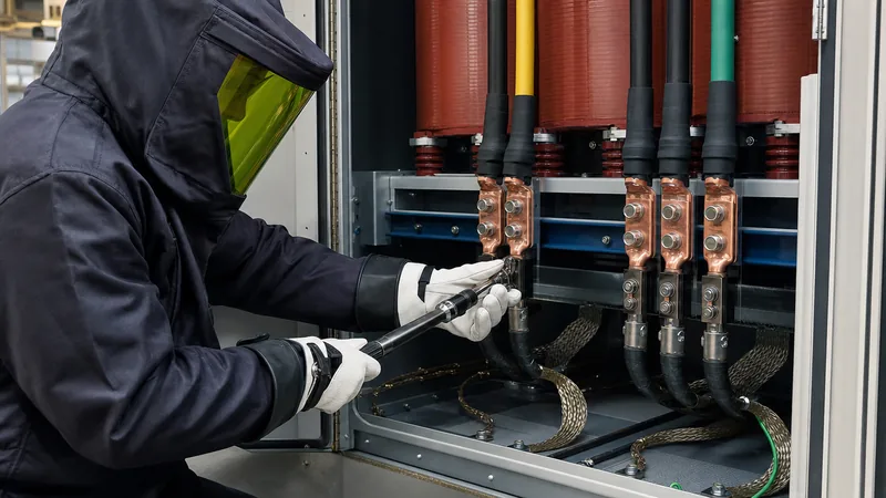
- Terminate conductors with calibrated torque: Strip conductor insulation neatly without nicking conductor strands. Crimp compression lugs using matched dies and a calibrated hydraulic crimper. Fasten lugs to terminal pads using Belleville conical spring washers and grade 8.8 steel or stainless steel hardware, tightening with a calibrated torque wrench to nameplate values.
- Install equipment and system grounding: Bond the transformer tank grounding pad to the facility earth grid using bare copper conductor sized according to IEC 60364-5-54 Table 54.2 or NEC Table 250.122. Bond the enclosure doors and internal frames across flexible braided copper jumpers.
- Connect auxiliary monitoring systems: Wire thermal sensors (PT100 RTDs or thermistors), dial thermometers, liquid level gauges, and pressure relief device alarm contacts to the marshalling terminal block using shielded twisted-pair cables.
Terminal Torque, Bolting, and Cable Sizing Standards
Proper torque values and conductor sizing are vital when wiring transformers to prevent resistive heating, metal oxidation, and catastrophic arc faults. Copper and aluminium lugs experience differential thermal expansion under varying load cycles; therefore, Belleville washers must be installed beneath standard flat washers to maintain continuous clamping pressure over temperature swings. Standard transformer capacities dictate conductor cross-section and lug bolting sizes, which engineers can cross-reference against standard transformer sizes.
The table below provides recommended bolt tightening torque standards across standard metric and imperial hardware grades used on transformer terminal pads:
| Hardware Size (Metric / Imperial) | Material Specification | Recommended Torque: Copper Bushing (N·m / lbf·ft) | Recommended Torque: Aluminium Pad (N·m / lbf·ft) | Minimum Lug Contact Area |
|---|---|---|---|---|
| M8 (5/16 in) | Grade 8.8 / SAE Grade 5 | 18 N·m (13 lbf·ft) | 15 N·m (11 lbf·ft) | 25 mm x 25 mm |
| M10 (3/8 in) | Grade 8.8 / SAE Grade 5 | 38 N·m (28 lbf·ft) | 32 N·m (24 lbf·ft) | 35 mm x 35 mm |
| M12 (1/2 in) | Grade 8.8 / SAE Grade 5 | 65 N·m (48 lbf·ft) | 55 N·m (41 lbf·ft) | 45 mm x 45 mm |
| M16 (5/8 in) | Grade 8.8 / SAE Grade 5 | 160 N·m (118 lbf·ft) | 135 N·m (100 lbf·ft) | 60 mm x 60 mm |
Always apply an anti-oxidation joint compound when bolting aluminium lugs to copper terminal pads or copper busbars to prevent galvanic corrosion and excessive interfacial resistance.
Pre-Energisation Testing and Inspection Checklist
Before energising a newly wired transformer, technicians must execute electrical acceptance tests to verify insulation integrity and termination accuracy. Never apply system voltage immediately following physical wiring; complete testing procedures as detailed in our guide on how to test a transformer. Ensure the following checklist passes before closing circuit breakers:
- Insulation Resistance Test: Apply 1,000 V to 2,500 V DC between primary windings, secondary windings, and ground per IEEE C57.12.90 clause 10. Insulation values should exceed 100 MΩ for low-voltage equipment and 1,000 MΩ for medium-voltage windings at 20 °C ambient.
- Voltage Ratio and Polarity Verification: Perform a Transformer Turns Ratio (TTR) test across all taps to verify that primary-to-secondary winding ratios match nameplate figures within 0.5% per IEC 60076-1 clause 10.3.
- Winding Resistance Test: Measure DC winding resistance across all phases using a micro-ohmmeter; phase-to-phase balance should match within 2% to ensure no crimp or internal connection faults exist.
- Grounding Continuity: Confirm low-resistance continuity (< 0.5 Ω) between the transformer tank, secondary neutral bushing (where applicable), and the earth grid.
- Phase Rotation Check: Verify primary supply phase sequence with a phase-rotation meter (A-B-C or 1-2-3) to ensure downstream motor loads will rotate in the correct intended direction.
Next steps: specifying and sourcing
When specifying or sourcing distribution units, padmounts, or substations, provide complete project parameters to ensure correct terminal orientation and bushing configurations. Submit your required primary and secondary voltages, BIL ratings, vector group, kVA rating, and cable entry arrangements (top or bottom entry) directly to our engineering team. Explore our range of oil-immersed distribution transformers, high-efficiency cast resin dry-type transformers, and factory-assembled pad-mounted transformers. For complete equipment sizing support or a fast, competitive quotation for your commercial or utility installation, visit our transformer quote page or get in touch with our application specialists via our contact page.
Frequently asked questions
how to connect transformer
To connect a transformer, first ensure the unit is de-energised and grounded. Connect primary supply conductors to the H (high-voltage) bushings and secondary load conductors to the X (low-voltage) terminals according to the nameplate schematic, torque all bolts to factory specification, and bond the tank and neutral to the grounding electrode.
how to wire up transformer
Wiring up a transformer involves landing the line conductors onto primary terminals (H1, H2, H3), connecting secondary feeders to output terminals (X1, X2, X3, and neutral X0), configuring any required series or parallel winding jumpers, torquing bolted lugs, and completing insulation resistance testing prior to energisation.
What is the difference between H and X terminals on a transformer?
H terminals designate the high-voltage side of the transformer (typically the primary winding in step-down applications), while X terminals designate the low-voltage side. In step-up applications, the source still connects to the voltage rating matching the supply, regardless of the H or X letter designation.
Do you need to ground the neutral on a transformer secondary?
Yes, on solidly grounded Wye secondary systems, the neutral terminal (X0) must be bonded to the grounding electrode conductor and enclosure ground bus. This stabilises phase-to-ground voltages and provides a low-impedance path to clear phase-to-ground faults safely.
Can you wire a single-phase transformer backwards to step up voltage?
Yes, standard passive transformers are bidirectional and can be back-fed by connecting source voltage to low-voltage X terminals to step up voltage at H terminals. However, inrush currents will be higher, and secondary tap ranges may not compensate accurately for voltage drop under load.
What torque should be used for transformer terminal lugs?
Terminal lug torque depends on hardware diameter and material. For standard Grade 8.8 steel hardware on copper pads, M10 bolts require 38 N·m (28 lbf·ft) and M12 bolts require 65 N·m (48 lbf·ft), fitted with Belleville washers to maintain clamping pressure.
Tags: how to wire up transformer how to connect transformer transformer wiring electrical connections transformer installation


