Key takeaways
- A low voltage circuit breaker operates up to 1,000 V AC or 1,500 V DC under IEC 60947-2 to provide controlled isolation, overload protection, and short-circuit interruption.
- IEC 60947-2 Category B circuit breakers possess a rated short-time withstand current (Icw), making them essential for time-graded selectivity at main switchboard incomers.
- Air circuit breakers serve as the primary low voltage power circuit breaker archetype for continuous currents up to 6,300 A with high short-time thermal ratings.
- A low voltage dc circuit breaker requires dedicated arc chutes and magnetic blowout coils because direct current lacks natural zero-crossing points during interruption.
- Service breaking capacity (Ics) indicates the actual operational fault clearing limit where a breaker remains operational without derating, unlike the ultimate limit (Icu).
Quick answer: A low voltage circuit breaker is an electromechanical protective device designed to automatically interrupt current flow during overloads and short circuits on systems operating at or below 1,000 V AC or 1,500 V DC, governed primarily by IEC 60947-2 and IEEE C37.13 standards.
In industrial and utility applications, selecting the correct lv circuit breaker dictates overall network reliability, operator safety, and switchboard uptime. As modern electrical architectures integrate high-fault sources such as battery energy storage systems, distributed generation, and large low-impedance distribution transformers, protective devices must handle extreme thermal and mechanical stresses. Specifying these units requires rigorous examination of breaking capacities, trip unit intelligence, trip coordination curves, and physical integration inside low-voltage switchboards assembled according to IEC 61439 standards.
Classification: Air, Moulded Case, and Miniature Types
Low voltage circuit breakers divide into three major constructional classes based on current carrying capacity, mechanical frame structure, and service duty.
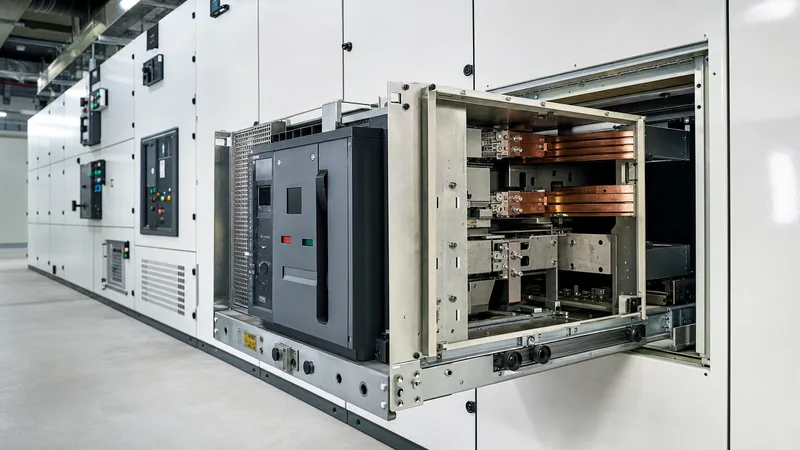
The traditional workhorse of the main distribution switchboard is the low voltage power circuit breaker, commonly constructed as an Air Circuit Breaker (ACB). Open-construction ACBs feature continuous ratings from 630 A to 6,300 A and breaking capacities exceeding 100 kA. Engineers specify withdrawable-type ACBs at the main incomer and bus-tie positions of unit substations because their drawout cassettes permit rapid maintenance, isolation verification, and mechanical racking without disassembling heavy busbar connections.
Moulded Case Circuit Breakers (MCCBs) protect sub-distribution circuits, large motor branches, and commercial feeders spanning 16 A to 1,600 A. Their components sit enclosed within a high-dielectric glass-filled polyester resin housing. While traditional MCCBs historically used thermal-magnetic releases, modern industrial installations demand electronic trip units (ETUs) with adjustable LSI (Long, Short, Instantaneous) protective curves. Miniature Circuit Breakers (MCBs) govern final distribution boards up to 125 A, providing DIN-rail mount overcurrent protection with fixed thermal-magnetic trip characteristics classified by B, C, or D curves under IEC 60898-1.
Ratings and IEC 60947-2 Selection Parameters
Specifying a low voltage circuit breaker requires matching published catalog characteristics against electrical network parameters defined by IEC 60947-2 clause 4.
The rated operational voltage ($U_e$) establishes the maximum line-to-line voltage for safe operation, while rated insulation voltage ($U_i$) defines dielectric test voltages. Protection engineers must differentiate between ultimate short-circuit breaking capacity ($I_{cu}$) and service short-circuit breaking capacity ($I_{cs}$). $I_{cu}$ defines the fault current a breaker can clear twice ($O - t - CO$ sequence) before requiring inspection or replacement. In contrast, $I_{cs}$ tests the breaker on a triple sequence ($O - t - CO - t - CO$) at a specified percentage of $I_{cu}$ (typically 50%, 75%, or 100%), verifying that the contacts can carry nominal current immediately afterwards without maintenance.
| Parameter | IEC 60947-2 Reference | Standard Units | Typical ACB Value | Typical MCCB Value |
|---|---|---|---|---|
| Rated Operational Voltage ($U_e$) | Clause 4.3.1.1 | V AC | 415 / 690 | 400 / 690 |
| Rated Continuous Current ($I_n$) | Clause 4.3.2.1 | A | 630 to 6,300 | 16 to 1,600 |
| Rated Insulation Voltage ($U_i$) | Clause 4.3.1.2 | V | 1,000 | 800 to 1,000 |
| Impulse Withstand Voltage ($U_{imp}$) | Clause 4.3.1.3 | kV | 12 | 8 |
| Ultimate Breaking Capacity ($I_{cu}$) | Clause 4.3.5.1 | kA rms | 50 to 150 | 25 to 100 |
| Service Breaking Capacity ($I_{cs}$) | Clause 4.3.5.2 | % of $I_{cu}$ | 100% | 50% to 100% |
| Short-Time Withstand ($I_{cw}$) | Clause 4.3.5.4 | kA rms (1s / 3s) | 42 to 100 | Limited or None (Cat A) |
| Utilization Category | Clause 4.4 | Class | Category B | Category A (mostly) |
Utilization Category B devices incorporate intentional short-time delays to ensure full discrimination with downstream Category A devices. A Category A low voltage breaker has no intentional delay for short-circuit tripping under instantaneous fault conditions, operating immediately to limit peak let-through energy.
Short-Circuit Sizing Calculation: Worked Engineering Example
A short-circuit calculation establishes the minimum breaking capacity required for a low voltage circuit breaker installed downstream of a step-down distribution transformer.
Consider an oil-filled transformer installed in an industrial facility with the following nameplate parameters: rated power $S_n = 2,500\text{ kVA}$, primary voltage $U_1 = 11\text{ kV}$, secondary line voltage $U_2 = 415\text{ V}$ (no-load voltage $U_{20} = 433\text{ V}$), and short-circuit impedance percentage $e_k = 6.0\%$. Assume an infinite upstream medium-voltage grid ($S_{sc} = \infty$) for conservative calculation.
First, calculate the secondary rated full-load current ($I_{r}$):
$$I_{r} = \frac{S_n}{\sqrt{3} \times U_2} = \frac{2,500,000}{\sqrt{3} \times 415} = 3,478.4\text{ A}$$
Next, determine the prospective symmetrical three-phase root-mean-square short-circuit current ($I_{sc}$) at the transformer secondary terminals:
$$I_{sc} = \frac{I_r}{\frac{e_k}{100}} = \frac{3,478.4}{0.06} = 57,973\text{ A} \approx 58.0\text{ kA}$$
Accounting for standard voltage variations per IEC 60909 with a voltage factor $c_{max} = 1.05$ applied to nominal 415 V:
$$I_{sc(max)} = \frac{c_{max} \times U_2}{\sqrt{3} \times Z_k} = 58.0 \times 1.05 = 60.9\text{ kA}$$
The peak asymmetrical make current ($I_{cm}$) requires multiplying the symmetrical RMS value by the peak factor $\kappa \times \sqrt{2}$. For an $R/X$ ratio typical of a 2,500 kVA unit ($X/R \approx 8$), IEC 60947-2 Table 2 mandates an $n$-factor of at least 2.1:
$$I_{cm} = 2.1 \times I_{cu} = 2.1 \times 60.9\text{ kA} = 127.9\text{ kA peak}$$
Specification conclusion: The main incomer low voltage circuit breaker requires a frame rating of at least 4,000 A continuous, a rated breaking capacity $I_{cu} \ge 65\text{ kA}$ at 415 V with $I_{cs} = 100\% I_{cu}$, and a short-time withstand rating $I_{cw} \ge 65\text{ kA}$ for 1 second. Selecting a Category B ACB with an electronic trip unit configured with selective time delay ensures clearance of faults without nuisance upstream tripping, protecting downstream assemblies detailed in our electrical switchgear guide.
Low Voltage DC Circuit Breaker Interruption Physics
A low voltage dc circuit breaker operates under fundamentally more demanding arc-extinction constraints than an alternating-current device due to the lack of a natural current zero.
In AC circuits, voltage and current pass through zero every half cycle (10 ms at 50 Hz, 8.33 ms at 60 Hz), which allows dielectric recovery across open contacts. In contrast, direct current maintains steady energy driving continuous contact plasma. The arc will not extinguish until arc voltage ($U_{arc}$) exceeds the system source voltage ($U_{dc}$), driving the rate of current change ($di/dt$) negative:
$$L \frac{di}{dt} = U_{dc} - U_{arc} - R \cdot i$$
To achieve this condition in photovoltaic arrays and battery energy storage installations, low voltage circuit breakers employ heavy magnetic blowout coils and multi-splitter deionising arc chutes. The magnetic coil generates a perpendicular Lorentz force ($F = I \times B$) that drives the electric arc at supersonic speeds into splitter plates. This action subdivides the main arc into multiple series micro-arcs, increasing total arc resistance and driving $U_{arc}$ rapidly above system voltage.
Furthermore, DC systems present high inductive time constants ($L/R$), especially in industrial traction or battery feeds governed by IEC 60947-2 Annex P. Engineers specifying a low voltage breaker for battery systems must confirm the rated breaking capacity matches the precise $L/R$ ratio of the installation (typically 15 ms to 30 ms for industrial battery rooms). Failing to account for circuit inductance will cause contact vaporization and flashover, risking an event like those explored in our article on arc flash safety.
Selectivity and Trip Coordination in LV Networks
Coordination between an upstream low voltage power circuit breaker and downstream devices ensures that only the protective device nearest to a fault opens.
Four distinct selectivity techniques operate within low-voltage industrial distribution networks:
- Current Selectivity (Amperometric): Relies on distinct pick-up current settings between series breakers. Effective primarily for low fault currents or high cable impedance between tiers, where the fault level drops significantly along the conductor run.
- Time Selectivity (Chronometric): Applies intentional progressive time delays (typically 100 ms to 300 ms increments) to upstream Category B breakers. The downstream breaker clears the fault instantaneously before the upstream timer completes its countdown.
- Energy Selectivity: Exploits the fast current-limiting dynamics of compact downstream moulded case breakers. The downstream breaker creates high arc resistance so quickly that the total let-through energy ($I^2t$) remains below the tripping threshold of the upstream feeder.
- Zone Selective Interlocking (ZSI): Utilises direct communication wiring between trip units. When a downstream breaker senses a fault, it clears the overcurrent immediately while sending a hardwired restraint signal to the upstream ACB, instructing it to hold its full time-delay. If a fault occurs between the two breakers (busbar fault), no blocking signal arrives, and the upstream ACB trips instantly (e.g., in 50 ms), mitigating arc energy.
Inspection and Factory Acceptance Testing Checklist
A structured testing protocol verifies that low voltage circuit breakers arrive without mechanical damage and perform within specified tripping tolerances before commissioning.
- Mechanical Integrity Verification: Check frame racking mechanisms, interlocks, contact wear indicators, and operating springs. Cycle the mechanism manually through open-charge-close sequences five consecutive times.
- Contact Resistance Measurement: Measure micro-ohm resistance across primary poles using a calibrated DC micro-ohmmeter at 100 A DC minimum. Pole resistances exceeding factory thresholds (typically 20 to 50 $\mu\Omega$ for large ACBs) indicate contact misalignment or oxidation.
- Dielectric Insulation Resistance: Apply a 1,000 V DC test voltage between phases, phase-to-earth, and across open contacts per IEC 60947-2 clause 8.3.3.4. Minimum insulation resistance must exceed 100 $\text{M}\Omega$.
- Primary Injection Secondary Verification: Inject calibrated currents into current transformers (CTs) or sensor coils to verify long-time, short-time, instantaneous, and ground-fault pickup points and trip timing curves against design documentation.
- Shunt Trip and Undervoltage Release Functional Checks: Verify tripping operation at minimum allowable control voltages (70% rated for shunt trips; 35% to 70% for undervoltage drops per IEC standards).
Next steps: specifying and sourcing
When submitting an enquiry for low voltage switchgear or replacement breakers, provide your single-line diagram, nominal operating voltage, prospective short-circuit levels ($I_{cu}/I_{cs}$), ambient temperature limits, and communication protocol requirements (Modbus TCP, IEC 61850). If sizing a low voltage dc circuit breaker for BESS or solar applications, clearly state system inductance and fault time constants ($L/R$). Explore our custom HV/LV switchgear solutions or integrated compact substations, and reach out to our engineering team directly through our quotation enquiry page to configure complete power assemblies.
Frequently asked questions
What is the difference between an ACB and an MCCB?
An Air Circuit Breaker (ACB) has an open construction, continuous ratings up to 6,300 A, and high short-time withstand current (Icw) for Category B selective incomers. A Moulded Case Circuit Breaker (MCCB) features an enclosed plastic housing, ratings up to 1,600 A, and generally acts as an instantaneous Category A current-limiting device.
What does Ics mean on a low voltage circuit breaker?
Service short-circuit breaking capacity (Ics) defines the fault level a breaker can clear three consecutive times while remaining fully operational to carry continuous load current. It is expressed as a percentage (50%, 75%, or 100%) of the ultimate breaking capacity (Icu).
Can an AC circuit breaker be used in DC applications?
Standard AC circuit breakers cannot be used in DC networks without direct manufacturer derating and series-wiring of poles. DC interruption lacks natural zero-crossings, requiring dedicated arc chutes, permanent magnets, and specific L/R ratings to extinguish sustained DC arcs.
What is Zone Selective Interlocking (ZSI)?
Zone Selective Interlocking is a hardwired communication scheme between upstream and downstream electronic trip units. Downstream breakers restrain upstream units during feeder faults, but if a busbar fault occurs, the upstream breaker trips without intentional delay, reducing arc energy.
Why is Utilization Category B important for main switchboards?
Utilization Category B provides a rated short-time withstand current (Icw), allowing the circuit breaker to withstand high fault currents for a set duration (typically 1 or 3 seconds). This capability allows downstream branch breakers time to isolate localized faults without de-energising the entire facility.
Tags: low voltage circuit breaker lv circuit breaker low voltage power circuit breaker low voltage dc circuit breaker low voltage breaker


