Key takeaways
- Underground switchgear operates in subsurface dry vaults, damp manholes, or fully submersible wet vaults subjected to IEEE C37.74 and IEC 62271-200 performance standards.
- Submersible underground distribution switchgear requires hermetically sealed 304 or 316L stainless steel tanks and IP68 ingress protection rated for continuous water immersion under heads exceeding 3 metres.
- Solid dielectric insulation utilizing vacuum interrupters encapsulated in cycloaliphatic epoxy eliminates SF6 gas tracking, maintenance venting, and catastrophic environmental leak risks.
- Pad-mounted surface enclosures require tamper-resistant penta-head fasteners and compartment barriers meeting IEEE C57.12.28 to withstand public vandalism and environmental intrusion.
- Specifying underground switchgear mandates explicit BIL ratings of 95 kV to 125 kV for 15 kV to 27 kV systems, along with 200 A loadbreak or 600 A/900 A deadbreak dead-front bushings.
Quick answer: Underground switchgear comprises medium-voltage switching, isolation, and overcurrent protection equipment engineered for installation in subsurface vaults, manholes, or ground-level pad enclosures. Designed to withstand subterranean moisture, flooding, and thermal constraints, this gear reliably sectionalises and protects underground medium-voltage networks operating up to 38 kV.
Urban density, severe weather events, and aesthetic zoning ordinances increasingly compel utilities and industrial site planners to bury medium-voltage distribution infrastructure. Transitioning circuits below grade removes overhead line exposure to windborne debris, vegetation contact, and vehicle collisions. However, placing switching equipment below the surface introduces aggressive operational stresses: perpetual ambient humidity, road-salt slurry ingress, confined-space heat retention, and complete subterranean submergence. Addressing these hazards requires robust design criteria, detailed in foundational guides on electrical distribution equipment and regional utility construction standards.
What is Underground Switchgear in Modern Power Networks?
Underground switchgear functions as the primary operational nexus for subsurface and pad-mounted medium-voltage distribution loops, providing localized circuit isolation, fault interruption, and automated network reconfiguration. Operating typically within 12 kV to 38 kV systems, underground distribution switchgear manages lateral feeder branches, commercial park feeds, and ties into modern transformer unit box-type substations. Unlike traditional indoor lineups, subterranean apparatus must deliver dead-front safety, ensuring that operating personnel have no exposure to energized primary conductors during switching.
Subsurface designs interface with high-voltage cabling through separable insulated connectors complying with IEEE 386. Technicians operate the switching ways using external mechanical linkages, manual operating handles, or automated motor actuators coupled to supervisory control and data acquisition (SCADA) networks. Whether installed in dry accessible vaults beneath city sidewalks or directly buried in flood-prone utility chambers, the equipment provides overcurrent fault clearing via vacuum interrupters, load-break sectionalizing via multi-position switches, and grounding facilities to establish safe clearances for downstream cable maintenance.
Subsurface Vault-Mount vs Pad-Mounted Enclosures
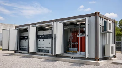
Selecting the structural housing geometry depends entirely on surface right-of-way constraints, civil infrastructure budgets, and flood plain hydrology. Pad-mounted switchgear occupies a surface footprint atop a precast concrete vault or box pad, housed in tamper-resistant, low-profile mild or stainless steel enclosures meeting IEEE C57.12.28. These enclosures employ dual-door access, recessed penta-head locking mechanisms, and labyrinthine baffles to prevent incidental probe contact by unauthorized personnel. Pad placement permits standard manual switching operations at grade, eliminating confined space entry permits and complex dewatering protocols.
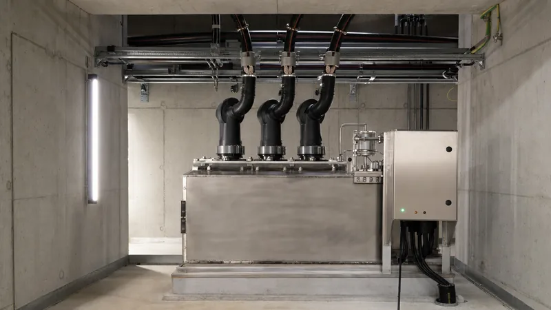
Conversely, vault-mounted underground switchgear resides entirely below grade inside cast-in-place or precast concrete chambers. These subterranean installations utilize fully submersible switch tanks certified to IEEE C37.74 or IEC 62271-200. The tanks are engineered to withstand continuous hydrostatic immersion under head levels typically specified at 3 metres (approximately 10 feet) or greater. When vault space is constrained, engineers configure the gear with top-mounted bushings and vertically oriented operating mechanisms, enabling utility teams to operate switches or test cable circuits from street level using hot sticks through vault grates.
Insulation Technologies: Solid Dielectric vs SF6 Gas
Dielectric medium selection directly dictates the structural footprint, operational lifespan, environmental compliance, and maintenance regime of underground installations. Historically, sulfur hexafluoride (SF6) gas served as the premier arc-quenching and insulating medium for compact subsurface switchgear. The electrical industry's ongoing transition away from fluorinated greenhouse gases has accelerated the adoption of solid dielectric technologies, as evaluated below:
| Engineering Metric | Solid Dielectric Switchgear | SF6 Gas-Insulated Switchgear |
|---|---|---|
| Insulating Medium | Cycloaliphatic Epoxy / EPDM Rubber | Sulfur Hexafluoride Gas (0.13-0.15 MPa) |
| Interrupting Medium | Hermetically Sealed Vacuum Bottle | SF6 Puffer or Vacuum Interrupter |
| Global Warming Potential (GWP) | 0 (Zero fluorinated emissions) | 24,300 (over 100-year horizon) |
| Operating Temperature Range | -40 °C to +65 °C | -30 °C to +50 °C (Liquefaction risks) |
| Pressure Monitoring Required | None (Zero internal gas pressure) | Temperature-compensated pressure gauges |
| Enclosure Penetration Risk | Impervious to moisture/air ingress | Gas leakage compromises insulation integrity |
| Dielectric Degradation Vector | Partial discharge tracking under void defect | Gas by-product formation (SOF2, HF) |
Solid dielectric architectures encapsulate vacuum interrupters within void-free, track-resistant cycloaliphatic epoxy resin. This solid barrier physically isolates the medium-voltage conductor from the surrounding environment. Because solid systems operate without pressurized chambers, they completely eliminate low-pressure lockouts, toxic gas testing, and routine density gauge inspections, offering a distinct operational advantage in confined vaults governed by strict environmental safety regulations.
Ratings and Standards for Underground Distribution Switchgear
Specifying subterranean medium-voltage apparatus requires alignment with international standard frameworks: IEEE C37.74 covers subsurface and vault-mounted load-interrupting switches, IEEE C37.60/IEC 62271-111 governs solid-dielectric vacuum reclosers, and IEC 62271-200 specifies metal-enclosed, gas-insulated or solid-insulated MV equipment. Dielectric insulation strength dictates the rated basic lightning impulse insulation level (BIL), which must match or exceed distribution system coordination parameters.
| Nominal Voltage Class (kV) | Rated Maximum Voltage (kV) | Power Frequency Withstand (kV rms) | BIL Rating (kV Peak) | Continuous Current (A) | Symmetrical Short-Circuit (kA rms) |
|---|---|---|---|---|---|
| 15.0 | 15.5 | 35 | 95 | 600 / 900 | 12.5 / 16.0 / 25.0 |
| 25.0 | 27.0 | 60 | 125 | 600 / 900 | 12.5 / 16.0 / 20.0 |
| 35.0 | 38.0 | 70 | 150 | 600 / 900 | 12.5 / 16.0 |
Terminations conform to IEEE 386 interfaces. Load-break ways utilize 200 A bushing wells with replaceable inserts, allowing energized disconnection via loadbreak elbows under rated operational voltages up to 25 kV. For main feeder highways, 600 A or 900 A deadbreak apparatus bushings accept bolted T-body cable connectors. Short-circuit performance requires continuous short-time current withstand ratings up to 25 kA for a full 3 seconds per IEC 62271-1 clause 6.5, ensuring mechanical bus stability and contact integrity during downstream network clearance events.
Network Schematics: Radial Feed, Loop Feed, and Ring Main Units
Circuit topology dictates network reliability, operational redundancy, and the number of active switchingways integrated into the underground switchgear chassis. The primary architectural choices mirror those detailed in utility engineering guides on radial feed vs loop feed networks, specifically configured for subterranean cable ducts:
- Radial Branch Configuration: Features a single medium-voltage source cable feeding one or multiple lateral protection taps through vacuum fault interrupters. While economical, an upstream cable fault de-energizes the entire radial section until physical repairs are completed.
- Open-Loop (Loop-Feed) Ring: Features two continuous 600 A incoming line ways and multiple 200 A or 600 A switched taps. Fed from two separate substations or substation bus sections, the ring remains open at a designated normally open tie point. In the event of a cable fault, personnel isolate the damaged line segment and close the tie switch, rapidly restoring service to all distribution transformers.
- Automated Ring Main Unit (RMU): Combines 3-way, 4-way, or 6-way modular compartments. Incorporating motorized interrupters, remote terminal units (RTUs), and directional fault indicators (FCIs), the RMU communicates with centralized SCADA to perform automatic fault location, isolation, and service restoration (FLISR) within seconds.
Engineers evaluate these schemes alongside the facility's overall single-line infrastructure, often cross-referencing a detailed power distribution diagram to verify protective relay coordination curves.
Submersible Vault Design, Drainage, and Corrosion Engineering
A subterranean equipment chamber must be engineered to mitigate chronic water pooling, chemical immersion, and restricted ventilation thermal derating. Subsurface vaults frequently experience total flooding where ground runoff carries dissolved road de-icing salts (calcium chloride, sodium chloride) and petroleum residues. To avoid galvanic corrosion and stress cracking, specify tanks fabricated entirely from ASTM A240 grade 304 or marine-grade 316L stainless steel, fully passivated post-welding. Mild steel components must be avoided below grade, even if zinc-primed or liquid-epoxy coated.
Ingress protection must meet IP68 under continuous hydrostatic heads of 3 metres for 14 days, verifying structural hermeticity across all dynamic shaft seals, viewing windows, and cable interface gaskets. Submersible equipment enclosures must incorporate sacrificial zinc or magnesium galvanic anode brackets to protect grounding connections in acidic or hyper-saline ground conditions. For concrete vault civil design, incorporate sump recesses with automatic submersible pumps, backwater check valves to prevent municipal storm sewer backflow, and sloped floor slabs (minimum 1:50 drop) pitching water clear of switchgear maintenance access points.
Step-by-Step Commissioning and Acceptance Procedures
Commissioning underground switchgear requires meticulous testing to verify dead-front insulation, vacuum bottle integrity, and trip circuit responsiveness before energization. Utility and contractor commissioning engineers should complete testing according to the following strict chronological sequence:
- Visual Inspection and Mechanical Cycling: Verify tank ground connections, mechanical interlocks, open/closed position indicators, and pressure relief vents. Mechanically cycle each manual and motorized operating switch five times consecutively to ensure frictionless linkage travel.
- Contact Resistance Testing (Micro-Ohm Measurement): Inject 100 A DC across each closed primary way using a micro-ohmmeter. Resistance values through vacuum interrupter contacts, internal busbars, and separable bushings should not exceed factory baseline figures (typically under 60 micro-ohms per phase path).
- Vacuum Interrupter Integrity (Hi-Pot Testing): Open the vacuum interrupter contacts and apply an AC high-potential test across the open gap per IEEE C37.60 Table 7 (e.g., 37.5 kV AC for 15 kV gear; 50 kV AC for 25 kV gear) for 60 seconds to verify vacuum envelope integrity.
- Insulation Resistance and VLF Tan-Delta: Perform 5 kV DC insulation resistance measurements between phases and from phase to ground (minimum 1,000 MΩ required). When integrated with long underground cables, execute very low frequency (VLF at 0.1 Hz) withstand and dissipation factor (Tan-Delta) diagnostics to identify baseline dielectric losses.
- Relay Injection and Protection Verification: Secondary-inject the electronic trip control module to verify inverse-time phase and ground overcurrent curves, confirming clearing signals trigger the mechanical trip actuator within factory design tolerances.
Specification and RFQ Procurement Checklist
Compiling an engineering request for quotation (RFQ) for vault-mounted or pad-mounted gear demands unambiguous electrical, structural, and control requirements. The checklist below highlights the critical engineering parameters project teams must compile:
- System Voltage and BIL Class: Nominal system voltage, maximum design voltage (15.5 kV, 27 kV, or 38 kV), and lightning impulse withstand level (95 kV, 125 kV, or 150 kV BIL).
- Continuous and Fault Current Ratings: Continuous bus ampacity (600 A or 900 A), switched tap current (200 A or 600 A), and symmetrical short-circuit withstand/clearing capacity (12.5 kA to 25 kA rms, 3 seconds).
- Enclosure Submergence Duty: Ingress rating (IP68 continuous submersion vs IP54 pad-mount), structural housing alloy (Grade 304 or 316L stainless steel), and vault depth/hydrostatic pressure head specifications.
- Switching Configuration: Total way count, defining number of source load-break switches (two-position, three-position with integral earth) versus overcurrent vacuum fault interrupters.
- Bushing Interfaces: IEEE 386 interface types (Interface 1 for 200 A loadbreak wells; Interface 2 or 3 for 600 A / 900 A deadbreak apparatus bushings), including bushing arrangement orientation (top-facing, front-facing, or lateral).
- Control, Automation, and Auxiliaries: Battery backup voltage, 24 VDC motor operators, Modbus/DNP3 SCADA protocols over serial communication or fiber optics, and current/voltage sensor accuracy classes for metering.
Next Steps: Specifying and Sourcing
Procuring reliable medium-voltage gear for subterranean distribution demands matching technical specifications precisely to vault conditions and operational safety protocols. Our engineering team designs and manufactures certified HV and LV switchgear, compact modular distribution units, and integrated transformer substations constructed to withstand severe underground environments.
To obtain an engineered proposal, forward your single-line schematics, vault structural elevations, continuous ampacity targets, and preferred bushing interface requirements to our technical specialists. Submit project files directly via our custom quotation page or consult with our project applications engineering department directly through our contact page.
Frequently asked questions
What is the difference between pad-mounted and underground switchgear?
Pad-mounted switchgear sits entirely at ground level mounted upon a concrete vault foundation within an air-insulated or solid-dielectric tamper-resistant outdoor metal enclosure. True underground switchgear is installed below grade inside chambers, manholes, or subterranean vaults, utilizing hermetically sealed, fully submersible IP68 construction to survive ongoing flooding.
Can underground switchgear operate when completely submerged in water?
Yes, provided the switchgear is rated for submersible duty under standards like IEEE C37.74 and sealed to IP68 ingress protection. Submersible units feature welded 304 or 316L stainless steel tanks, sealed rotary shaft glands, and fully watertight IEEE 386 separable insulated connector bushings rated for continuous hydrostatic heads.
Why is solid dielectric insulation replacing SF6 gas in underground switchgear?
Solid dielectric designs eliminate SF6 greenhouse gas emissions, low-pressure freeze lockouts, and mandatory environmental reporting regulations. By encapsulating vacuum interrupters within void-free cycloaliphatic epoxy or specialized EPDM rubber, solid dielectric apparatus operates maintenance-free without internal gas pressure sensors, reducing long-term lifecycle costs.
What maintenance is required for vault-installed underground switchgear?
Maintenance involves periodic vault dewatering, external visual inspection for tank corrosion or anode depletion, and testing separable connector insulation surfaces. Annual testing should include micro-ohm contact resistance measurements, high-potential vacuum integrity checks, and functional trip tests of the electronic protective relays and motor actuators.
What standards govern underground distribution switchgear design?
Key governing standards include IEEE C37.74 for subsurface load-interrupting switches, IEEE C37.60 / IEC 62271-111 for fault interrupters and reclosers, IEC 62271-200 for metal-enclosed medium-voltage equipment, and IEEE 386 for 200 A and 600 A separable insulated connector bushing interfaces.
Tags: underground switchgear underground distribution switchgear box-type substations MV switchgear submersible switchgear