Key takeaways
- Low voltage switchgear operates up to 1000 V AC or 1500 V DC, serving as the central electrical distribution and protection hub downstream of distribution transformers.
- IEC 61439-2 defines assembly verification rules, replacing obsolete Type Tested Assembly (TTA) and Partially Type Tested Assembly (PTTA) categories with design verification methods.
- Internal separation forms (Form 1 to Form 4b) isolate busbars, functional units, and terminals to protect personnel and prevent internal fault propagation.
- Busbar sizing requires dynamic stress verification against peak withstand current (Ipk) and thermal verification against short-time withstand current (Icw) for designated durations.
- Evaluating low voltage switchgear manufacturers requires reviewing type-test certificates from accredited laboratories, arc-fault mitigation testing, and factory routine test protocols.
Quick answer: Low voltage switchgear is an integrated assembly of electrical switching, interrupting, metering, and protective devices rated up to 1000 V AC or 1500 V DC. It controls, protects, and isolates industrial circuits, motor control systems, and downstream distribution networks from short circuits, overloads, and earth faults.
In heavy industrial plants, data centres, and commercial infrastructure, lv switchgear serves as the primary gateway between the step-down distribution transformer and secondary branch distribution boards. Specifying low voltage assemblies requires rigorous evaluation of nominal busbar ratings, short-circuit withstand capabilities, and internal partitioning to protect personnel during operation and maintenance. Ensuring compliance with modern standards such as IEC 61439 Low-Voltage Switchgear Engineering Guide or North American ANSI/IEEE standards prevents costly catastrophic switchboard failures and unscheduled plant outages.
What Is Low Voltage Switchgear and How Does It Operate?
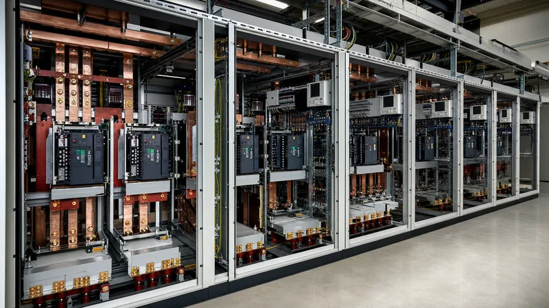
Low voltage switchgear functions as the main electrical apparatus that receives power from incoming sources—such as transformers, generators, or energy storage systems—and distributes it safely to multiple feeder circuits. Unlike a standard domestic or light-commercial distribution board, an industrial low voltage assembly incorporates heavy-duty air circuit breakers (ACBs), moulded case circuit breakers (MCCBs), copper or aluminium busbars, protection relays, and power monitoring instruments enclosed within a modular steel structure.
Under normal conditions, the switchgear allows plant operators to energise, de-energise, and sectionalise portions of the electrical network manually or via remote supervisory control and data acquisition (SCADA) systems. When an electrical fault occurs, such as a short circuit or an earth leakage, integrated protective relays detect abnormal current waveforms via current transformers (CTs) and trigger the circuit breaker opening mechanism in milliseconds. According to fundamental principles detailed in our electrical switchgear engineering guide, this swift isolation restricts thermal and electrodynamic damage to downstream cabling and adjacent feeder equipment.
Key Standards: IEC 61439 vs ANSI/IEEE C37.20.1 and UL 1558
International engineering specifications for low voltage switchboards diverge between the International Electrotechnical Commission (IEC) framework and the North American ANSI/IEEE/NEMA/UL regulatory framework. Selecting the correct manufacturing standard dictates clearance distances, temperature rise limits, and verification testing.
Under IEC 61439-1 (General Rules) and IEC 61439-2 (Power Switchgear and Controlgear Assemblies - PSC Assemblies), the historical classification of type-tested (TTA) and partially type-tested (PTTA) assemblies has been eliminated. Compliance now requires design verification through three distinct methods: test, comparison with a tested reference design, or calculation. Assemblies must pass 13 verification requirements, covering temperature rise limits (IEC 61439-1 clause 10.10), dielectric properties (clause 10.9), and short-circuit withstand strength (clause 10.11).
Conversely, North American installations adhere to UL 1558 and ANSI/IEEE C37.20.1 for metal-enclosed low-voltage power circuit breaker switchgear. While IEC assemblies permit non-segregated withdrawable units, UL 1558 demands compartmentalised construction with full barriers between circuit breakers, bus compartments, and cable termination sections. Additionally, UL 891 governs standard dead-front switchboards, which provide less internal segregation than UL 1558 switchgear but represent a lower capital expenditure for light-duty commercial facilities.
Forms of Internal Separation in LV Switchgear Assemblies
Forms of internal separation defined by IEC 61439-2 Table 101 specify physical barriers within an assembly to protect operators against direct contact with live components and mitigate the risk of internal arc faults migrating between compartments.
Engineers must match the form of separation to the criticality of the facility and maintenance protocols:
| Separation Form | Busbars Separated from Functional Units | Functional Units Separated from Each Other | Terminals Separated from Busbars | Terminals Separated from Functional Units | Typical Industrial Application |
|---|---|---|---|---|---|
| Form 1 | No | No | No | No | Basic sub-distribution, non-critical lighting panels |
| Form 2b | Yes | No | Yes | No | Light industrial plants with de-energised maintenance |
| Form 3b | Yes | Yes | Yes | No | Commercial HVAC, industrial continuous process feeders |
| Form 4a | Yes | Yes | Yes | Yes (terminals in same compartment as unit) | Heavy process industry, marine power systems |
| Form 4b | Yes | Yes | Yes | Yes (terminals in separate external compartments) | Data centres, hospitals, offshore platforms, continuous manufacturing |
In critical facilities, Form 4b is preferred because an electrician can terminate or test cables for a single feeder compartment without shutting down the main horizontal busbar or exposing hands to neighbouring live outgoing circuits. In high-risk environments, combining Form 4b separation with passive venting or optical arc detection provides comprehensive mitigation against destructive arc flashes, as covered in our guide on what is arc flash and safety containment.
Busbar Sizing and Short-Circuit Withstand Calculation
Busbar design requires mechanical verification against peak electrodynamic stress and thermal verification against short-time current heating.
Consider an industrial switchboard fed by a 2000 kVA, 400 V, 3-phase, 50 Hz transformer with an impedance voltage ($u_k$) of 6.0%. Calculate the prospective symmetrical short-circuit current ($I_k''$) and the minimum copper busbar cross-sectional area required to withstand this fault for $t = 1.0\text{ s}$.
- Determine rated transformer secondary current ($I_n$):
$$I_n = \frac{S}{\sqrt{3} \times V} = \frac{2000\text{ kVA}}{\sqrt{3} \times 400\text{ V}} = 2886.75\text{ A}$$ - Calculate symmetrical prospective short-circuit current ($I_k''$):
Assuming an infinite upstream medium-voltage network:
$$I_k'' = \frac{I_n}{u_k / 100} = \frac{2886.75\text{ A}}{0.06} = 48,112.5\text{ A} \approx 48.11\text{ kA}$$The rated short-time withstand current ($I_{cw}$) of the main busbar assembly must therefore be specified at not less than 50 kA for 1 second. - Calculate peak withstand current ($I_{pk}$):
Per IEC 61439-1 Table 7, for short-circuit currents between 20 kA and 50 kA, the standard factor $n$ (ratio of peak to RMS) is 2.1:
$$I_{pk} = I_{cw} \times n = 50\text{ kA} \times 2.1 = 105\text{ kA}$$The busbar supports, insulator spacing, and structural bracing must be engineered to withstand the peak mechanical electromagnetic repulsion generated by a 105 kA crest. - Calculate minimum busbar thermal cross-sectional area ($S_{min}$):
Using the adiabatic thermal equation from IEC 60364-5-54:
$$S_{min} = \frac{I_{cw} \times \sqrt{t}}{k}$$Where $k = 176\text{ A}\cdot\text{s}^{1/2}/\text{mm}^2$ for bare copper busbars running from an initial operating temperature of 70 °C to a final fault limit of 200 °C:
$$S_{min} = \frac{50,000 \times \sqrt{1.0}}{176} = 284.1\text{ mm}^2$$
While $284.1\text{ mm}^2$ satisfies thermal fault heating, continuous current carrying capacity governs actual conductor selection. For a 3200 A rated busbar operating at 35 °C ambient inside an IP54 enclosure, engineers typically specify multiple laminations, such as two or three parallel $100\text{ mm} \times 10\text{ mm}$ electrolytic copper bars per phase, to combat skin effect and maintain internal temperatures below IEC 61439-1 limits.
Selecting Components: Air Circuit Breakers vs Moulded Case Circuit Breakers
Selecting between air circuit breakers (ACBs) and moulded case circuit breakers (MCCBs) depends on the nominal current rating, duty cycle, selective coordination requirements, and physical space constraints.
Air circuit breakers, typically utilised from 800 A up to 6300 A, serve as main incomers and critical bus ties. ACBs are predominantly built to IEC 60947-2 Utilisation Category B, meaning they possess a rated short-time withstand current ($I_{cw}$) that permits intentional time delays (up to 1.0 second). This intentional delay allows downstream protective devices to clear local faults without tripping the main incomer, maintaining full system selectivity.
Moulded case circuit breakers, deployed from 16 A up to 1600 A, generally fall under Utilisation Category A, where instantaneous tripping occurs without an intentional delay during high-level short-circuit currents. While modern current-limiting MCCBs clear faults in under 10 milliseconds—reducing energy let-through ($I^2t$) to downstream machinery—they lack the extensive withstand capability required for upstream discrimination in complex primary distribution architectures.
Evaluating Low Voltage Switchgear Manufacturers for Industrial Projects
Procuring reliable assemblies from low voltage switchgear manufacturers requires verifying physical engineering capacity, testing documentation, and quality assurance processes rather than relying solely on catalogue declarations.
When evaluating bids for industrial power distribution projects, engineering procurement teams should audit the following key technical items:
- Third-Party Type Test Certification: Demand full type-test certificates from internationally accredited testing authorities (e.g., ASTA, KEMA, CESI, or DEKRA) demonstrating compliance with IEC 61439-2 or UL 1558. Confirm that the busbar arrangement and enclosure dimensions shown in the test reports match the proposed production drawings.
- Enclosure Ingress Protection (IP) and Mechanical Impact (IK) Ratings: Confirm certified testing for the specified degree of protection (such as IP42 for indoor clean environments, IP54 for dusty industrial basements, or NEMA 3R/4X for outdoor packages).
- Arc Fault Containment Certification: Require evidence of internal arc testing in accordance with IEC TR 61641 criteria 1 to 7 (for personnel and assembly protection) under prospective fault currents matching the transformer capacity.
- Factory Routine Testing: Confirm that 100% of manufactured panels undergo dielectric withstand tests, secondary wiring continuity checks, mechanical interlocking verification, and functional trip tests before export, as detailed in our switchgear manufacturers sourcing guide.
Next steps: specifying and sourcing
When preparing an RFQ for low voltage switchboards or package distribution equipment, provide your single-line diagram (SLD), prospective short-circuit fault levels, environmental conditions, and desired form of internal separation. To review factory-engineered distribution assemblies, explore our medium and low voltage switchgear range or combine primary equipment using an integrated prefabricated transformer substation. Our engineering team assists engineering teams with busbar sizing calculations, protection coordination studies, and custom footprint layouts. Contact our technical team or submit your design documentation directly through our switchgear quotation page to receive a technical proposal.
Frequently asked questions
What is the difference between low voltage switchgear and switchboards?
Low voltage switchgear typically refers to heavy-duty, compartmentalised assemblies featuring draw-out air circuit breakers with high short-time withstand ratings (IEC 61439-2 / UL 1558). Switchboards (such as UL 891) are front-accessible, less compartmentalised units housing group-mounted moulded case circuit breakers designed for standard commercial power distribution.
What is the rated insulation voltage for low voltage switchgear?
The rated insulation voltage (Ui) for industrial low voltage switchgear is typically 1000 V AC (50/60 Hz) or 1500 V DC under IEC standards. This rating governs dielectric testing, clearance, and creepage distances to guarantee insulation integrity during transient overvoltages.
What does Form 4b separation mean in low voltage switchgear?
Form 4b separation isolates busbars from functional units, separates all functional units from one another, and segregates outgoing cable terminals from both the busbars and functional units. This ensures technicians can terminate cables safely without exposing themselves to adjacent energised circuits.
How is the short-circuit rating of an LV switchboard determined?
The rating is determined by calculating the prospective symmetrical short-circuit current from the feeding transformer's kVA and impedance percentage (%Z). The switchgear main busbar and circuit breakers must have an Icw rating equal to or higher than this fault current for 1 or 3 seconds.
Can copper and aluminium busbars be mixed in low voltage switchgear?
Direct physical contact between copper and aluminium busbars is prohibited due to galvanic corrosion and differential thermal expansion. When transitions are unavoidable, manufacturers must utilise bi-metallic transition washers or electroplated tin barriers to prevent joint degradation.
Tags: low voltage switchgear lv switchgear low voltage switchgear manufacturers switchgear sourcing


