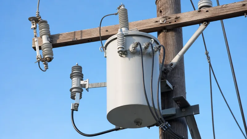
Key takeaways
- A single-phase pole-mounted transformer uses high-voltage bushings H1 and H2 for primary input and low-voltage terminals X1, X2, and X3 for split-phase secondary output.
- Connecting secondary coils in series provides 120/240 V three-wire split-phase service, with the centre-tap terminal X2 grounded as the neutral conductor under IEEE C57.12.20.
- Single-bushing transformers (H1 only) operate strictly on grounded wye systems where the tank and one end of the primary winding connect directly to the system neutral.
- Three single-phase units can be interconnected in wye-wye, delta-delta, or open-delta configurations to serve three-phase industrial and commercial loads.
- Effective equipment grounding requires bonding the tank ground lug, low-voltage neutral X2, and surge arrester base to a continuous multi-grounded distribution neutral.
Quick answer: A single phase pole mounted transformer wiring diagram shows the electrical connections between medium-voltage primary lines (bushing terminals H1 and H2) and low-voltage secondary services (terminals X1, X2, and X3). It illustrates how high distribution voltages (typically 2.4 kV to 34.5 kV) are stepped down to deliver 120/240 V single-phase, three-wire split-phase power or banked three-phase service.
Overhead distribution networks rely heavily on pole-mounted units to deliver final utilisation voltages to residential, agricultural, and light commercial consumers. Understanding the schematic and terminal layouts of these units ensures safe hookups, balanced loading, and compliance with grid codes such as IEEE C57.12.20 and IEC 60076. Whether reviewing a replacement schematic in the field or planning an overhead service drop, a clear command of the internal winding arrangements, bushing designations, and protective grounding bonds is essential for electrical engineers and line technicians. For broader mechanical and construction context, consult our comprehensive guide to single phase pole mounted transformers.
Understanding the Single Phase Pole Mounted Transformer Wiring Diagram
A single phase pole mounted transformer wiring diagram represents the internal core-and-coil assembly, polarity orientations, external bushing connections, and protective hardware of an overhead distribution transformer. The schematic illustrates two distinct electrical sections: the primary high-voltage (HV) winding and the secondary low-voltage (LV) winding, magnetically linked by a grain-oriented silicon steel or amorphous metal core.
In standard utility diagrams, the primary winding is designated with an "H" prefix and the secondary winding with an "X" prefix. ANSI and IEEE standards stipulate subtractive polarity for single-phase distribution units rated up to 8.66 kV with secondary ratings up to 600 V (and 200 kVA or below). Larger ratings or non-standard configurations may exhibit additive polarity. On a subtractive polarity unit, terminal H1 is positioned adjacent to terminal X1 across the tank wall, which governs the instantaneous phase angle between the primary line and secondary feeder conductors. Interpreting these terminal notations correctly prevents cross-phase dead shorts when banking transformers or tying into existing secondary distribution lines. To understand standard graphical drafting symbols used across these drawings, refer to our transformer symbol schematic guide.
Primary HV Terminal Markings and Connections (H1 and H2)
Primary connections on an overhead transformer depend on whether the supply feeder is a multi-grounded four-wire wye system or an ungrounded or delta three-wire distribution system. On standard dual-bushing units, the high-voltage winding terminates at porcelain or polymer bushings marked H1 and H2 mounted on the tank cover.
For a phase-to-phase installation on a delta distribution system, terminal H1 connects to one primary phase line via a fused cutout switch, while terminal H2 connects to a second phase line through an identical protective cutout. Conversely, on a four-wire wye distribution line, terminal H1 connects to one energised phase conductor, and H2 is bonded directly to the system neutral conductor and tank ground. Single-bushing transformers (often called single-phase ground-return or grounded-wye units) feature only an H1 bushing; the second end of the primary high-voltage winding is internally pre-bonded to the transformer tank, which must be solidly connected to the continuous multi-grounded neutral (MGN) conductor. Failure to bond this internal ground path to an effective neutral will result in full primary phase potential across the tank body, presenting an immediate electrocution hazard and preventing fuse clearance during faults.
Secondary LV Split-Phase Connections (X1, X2, and X3)
Secondary low-voltage terminals on a standard residential pole mounted transformer diagram supply a three-wire, single-phase 120/240 V split-phase distribution circuit. Modern distribution units contain two internal 120 V secondary coils wound around the core, providing flexibility for either parallel (120 V only) or series (120/240 V) configurations.
In the standard series connection:
- Terminal X1: Represents the start of the first secondary coil, supplying 120 V to neutral and full 240 V across to X3. This is one of the energised "hot" legs feeding the service entrance.
- Terminal X2: Serves as the internal common series connection (centre-tap) between the two secondary windings. This terminal connects directly to the service neutral conductor and is bonded to the transformer tank and earth ground.
- Terminal X3: Represents the finish of the second secondary coil, providing the second 120 V energised line (180 degrees out of phase with X1) and establishing the 240 V line-to-line potential required for heavy electrical loads such as HVAC units and industrial heaters.
For detailed comparisons between various single-phase winding strategies and their industrial wiring practices, read our complete overview of transformer wiring diagrams.
Terminal Designation and Voltage Configuration Chart
Field technicians must verify nominal line-to-ground and line-to-line voltages across both primary and secondary terminals before connecting consumer loads. The table below outlines standard terminal arrangements for single-phase distribution equipment built to IEEE C57.12.20 and IEC 60076 standards.
| Terminal Pair | Primary / Secondary | Nominal Voltage (Typical) | System Function | Earthing / Bonding Requirement |
|---|---|---|---|---|
| H1 to H2 | Primary (HV) | 2,400 V – 34,500 V | Phase-to-phase or phase-to-neutral feed | H2 bonded to neutral on grounded wye grids |
| H1 to Ground | Primary (HV) | V_line / 1.732 (Wye) | Phase-to-earth stress insulation rating | Must withstand rated basic impulse level (BIL) |
| X1 to X3 | Secondary (LV) | 240 V AC | Line-to-line full-capacity service | Isolated from earth; ungrounded circuit conductors |
| X1 to X2 | Secondary (LV) | 120 V AC | Line-to-neutral branch power (Leg A) | X2 bonded directly to tank and ground rod |
| X3 to X2 | Secondary (LV) | 120 V AC | Line-to-neutral branch power (Leg B) | X2 bonded directly to tank and ground rod |
| Tank Lug | Hardware Ground | 0 V Reference | Chassis fault return and personnel safety | Solidly bonded to copper down-lead and earth electrode |
Correct insulation resistance verification across each pair is crucial during commissioning, adhering to standard test procedures described in our engineering guide on oil filled transformers.
Pole Transformer Diagram for Three-Phase Bank Arrangements
A pole transformer diagram frequently depicts three individual single-phase overhead transformers interconnected on a single utility crossarm or cluster mount to supply three-phase electrical power. Utilities use this approach to serve commercial and light industrial facilities requiring 208Y/120 V, 480Y/277 V, or 240/480 V delta power without installing expensive pad-mounted gear.
Three primary banking topologies dominate overhead line design:
- Wye-Wye (Y-Y) Banks: The primary H2 bushings of all three units connect to a common neutral point, which ties directly to the distribution system neutral. On the secondary side, all X2 terminals connect together to form the secondary neutral point, delivering balanced three-phase four-wire service (such as 208Y/120 V). Both primary and secondary neutrals must be solidly interconnected and grounded to suppress ferroresonance and third-harmonic voltage distortions.
- Delta-Delta (Δ-Δ) Banks: Primary windings connect in series across the phase lines (H1 of unit A to H2 of unit B, H1 of B to H2 of C, H1 of C to H2 of A). Secondary windings follow an identical closed-loop arrangement (X1 to X3 across units). This configuration provides high reliability because it can continue operating at reduced capacity if one unit fails.
- Open-Delta / Open-Wye Banks: Operating with only two single-phase units, an open bank provides three-phase power at 57.7% of the capacity of a full three-unit delta bank. One transformer (the "lighting unit") has its secondary centre tap (X2) grounded to provide 120/240 V single-phase loads, while the second transformer (the "power unit") operates in series to provide the third phase conductor (often called the "high leg" or wild leg, carrying 208 V nominal to neutral).
Step-by-Step Wiring and Grounding Installation Procedure
Executing an overhead transformer installation requires rigorous compliance with the National Electrical Safety Code (NESC), NEC Article 450, and local utility service standards. Follow this sequence when wiring a single-phase pole-mounted unit:
- Mount and Inspect the Tank: Hoist the unit onto the pole using rated lifting lugs. Inspect the tank for shipping damage, oil leaks, correct dielectric oil levels via the level plug, and verify the internal tap changer matches the measured feeder voltage.
- Establish the Pole Ground Grid: Drive a minimum 16 mm diameter copper-clad ground rod at the pole base to achieve a target resistance below 25 ohms. Run a continuous, uninsulated #4 or #2 AWG solid copper grounding down-lead from the pole top to the ground rod.
- Bond Tank and Secondary Neutral: Connect the tank grounding lug solidly to the pole grounding down-lead. Install a grounding strap from the LV secondary neutral terminal (X2) directly to the transformer tank ground pad.
- Install Primary Surge Protection: Mount a metal-oxide varistor (MOV) surge arrester adjacent to the primary cutout switch. Route the arrester discharge lead via the shortest, straightest possible path directly to the tank ground terminal to minimise inductive impedance under lightning transients.
- Wire the Primary HV Connections: Connect the cutout switch drop-lead to terminal H1 using hot-line clamps. On dual-bushing units installed on wye lines, run the H2 lead to the system neutral conductor.
- Wire the Secondary Service Drop: Connect the consumer triplex or quadruplex service entrance conductors to terminals X1, X2 (neutral), and X3 using rated compression or mechanical lugs, torquing all terminal nuts to manufacturer specifications to prevent thermal cycling failure.
Next steps: specifying and sourcing
When specifying single-phase overhead distribution transformers for utility electrification, rural grid expansions, or industrial installations, provide your manufacturer with precise technical parameters. These include primary and secondary system voltages, required kVA capacity (standard ratings range from 10 kVA to 333 kVA), basic impulse insulation level (BIL), frequency (50 Hz or 60 Hz), and required winding material (copper or aluminium). Explore our engineered product offerings including high-efficiency pole-mounted transformers and complete utility-grade oil-immersed transformers built to IEEE C57.12.20 and IEC standards. To request custom electrical schematics, type test reports, or tender pricing, submit your project schedule to our engineering design desk through our transformer quotation portal.
Frequently asked questions
How do you read a single phase pole mounted transformer wiring diagram?
Identify the high-voltage primary terminals marked H1 and H2 and the low-voltage secondary terminals marked X1, X2, and X3. Follow the line feeds from the primary cutouts to the primary terminals, observe whether the primary is connected phase-to-phase or phase-to-neutral, and trace the secondary split-phase outputs from X1, X2 (grounded neutral), and X3 to the service drop conductors.
What do H1, H2, X1, X2, and X3 represent on a pole transformer?
H1 and H2 represent the primary high-voltage winding terminals connected to the distribution grid. X1, X2, and X3 denote the low-voltage secondary winding terminals, where X1 and X3 provide hot service legs and X2 serves as the centre-tap neutral bonded to ground.
How is a 120/240V split-phase connection wired on a pole-mounted transformer?
The two internal 120 V secondary coils are connected in series. Terminal X1 connects to the first hot line, terminal X3 connects to the second hot line, and terminal X2 is connected to the midpoint between the coils, creating a neutral that yields 120 V to either line and 240 V line-to-line.
Why is the X2 terminal grounded on a pole transformer?
Terminal X2 is grounded to stabilise the secondary system voltage with respect to earth, prevent secondary lines from floating to dangerous high-voltage levels during primary-to-secondary insulation breakdown, and provide an intentional low-impedance path to trip protective breakers during line-to-ground faults.
Can you wire three single-phase pole transformers for three-phase power?
Yes, three single-phase pole-mounted transformers can be banked together in wye-wye, delta-delta, or wye-delta configurations. Their primary terminals (H1, H2) and secondary terminals (X1, X2, X3) are interconnected according to standard banking schematics to deliver balanced three-phase commercial or industrial voltages.
Tags: single phase pole mounted transformer wiring diagram pole mounted transformer diagram pole transformer diagram overhead distribution transformer transformer wiring


