Key takeaways
- A single phase pole mounted transformer steps medium-voltage overhead distribution down to low utilisation voltages, typically 120/240 V split-phase or 240/480 V.
- Standard capacities range from 5 kVA to 500 kVA, governed internationally by IEEE C57.12.20 and IEC 60076 standards.
- Completely Self-Protected (CSP) designs incorporate integral primary weak-link fuses, secondary circuit breakers, and tank-mounted surge arresters directly into the tank assembly.
- Wound-core architectures using grain-oriented silicon steel (CRGO) or amorphous alloys yield low no-load losses and robust short-circuit withstand capabilities.
- Routine installation requires strict adherence to pole loading limits, grounding electrode resistance below 25 ohms, and precise clearance buffers specified in NESC or local grid codes.
Quick answer: A single phase pole mounted transformer is an overhead electrical distribution unit mounted on utility poles that steps down medium distribution voltages (such as 11 kV, 13.8 kV, or 34.5 kV) to single-phase low-voltage service (typically 120/240 V or 230 V) for residential, rural, and light commercial consumers.
Overhead electricity networks worldwide rely heavily on the overhead pole platform to deliver low-voltage power directly at the point of consumption. In regions using North American grid designs, single-phase lateral taps from three-phase medium-voltage feeders feed individual or clustered domestic premises through these pole-top units. In contrast to ground-level installations, an overhead unit requires minimal ground real estate, reduces civil engineering costs, and provides physical isolation from public foot traffic and terrestrial wildlife.
Specifying an overhead transformer demands a comprehensive understanding of core and coil topologies, mechanical mounting constraints, thermal dissipation, and fault withstand capabilities. Whether evaluating a standard conventional build or a self-protected package, engineering teams must weigh total ownership costs, efficiency regulations like DOE 2016 or EU Ecodesign, and regional dielectric safety mandates to ensure reliable, multi-decade grid performance.
What is a Single Phase Pole Mounted Distribution Transformer?
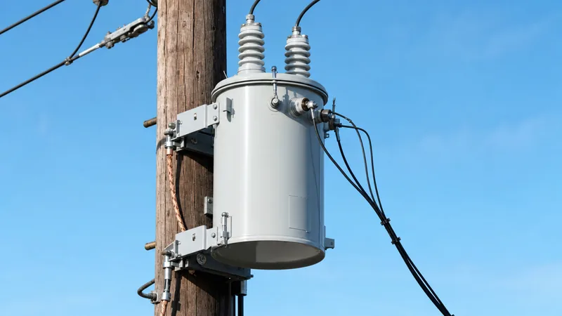
A single phase pole mounted distribution transformer is a liquid-immersed, outdoor electrical apparatus designed for elevated mechanical mounting on wood, concrete, or steel utility poles to deliver final voltage conversion. Standardized under IEEE C57.12.20 and IEC 60076 specifications, these units accept primary phase-to-ground or phase-to-phase medium voltages ranging from 2,400 V up to 34,500 V GrdY, stepping down to standard utilisation levels such as 120/240 V three-wire split-phase, 240/480 V, or 230 V single-phase.
Power ratings for pole-top units typically span from 5 kVA to 167 kVA for individual domestic services, extending up to 333 kVA or 500 kVA for rural pumping, agricultural processing, and light industrial feeders. The core-and-coil assembly is housed within a hermetically sealed, cylindrical mild-steel or stainless-steel tank filled with inhibited electrical insulating oil conforming to ASTM D3487 or IEC 60296. For comprehensive background on how these units compare with larger substation equipment, consult our distribution transformer guide.
Electrically, the transformer isolates the primary medium-voltage distribution network from the customer’s service drop while offering controlled percent impedance (%Z)—typically between 1.5% and 3.5%—to limit downstream fault currents without causing excessive operational voltage drop during inrush conditions.
Conventional vs CSP Single Phase Distribution Transformer Designs
The operational difference between conventional and Completely Self-Protected (CSP) single phase distribution transformer designs lies in whether system protection hardware is installed externally on the crossarm or integrated within the transformer tank itself.
Conventional overhead transformers consist solely of the core, windings, oil-filled tank, and low- and high-voltage bushings. To operate safely, a conventional unit requires the utility or EPC contractor to field-install external protective equipment on the pole: an external fused cutout switch equipped with an expulsion fuse link, a separate surge arrester mounted to the crossarm, and an external low-voltage disconnect if required. While conventional designs give field crews clear visual confirmation of a blown fuse via the cutout drop-out mechanism, they require higher field labour and wider pole-top physical clearances.
A CSP single phase pole mounted transformer integrates these protective elements directly into the factory package. Internally, a primary weak-link fuse protects the high-voltage system from internal core-coil failure, while an internal secondary circuit breaker with an external operating handle protects against downstream secondary short circuits and thermal overload. Integral direct-mounted tank surge arresters suppress lightning and switching surges right at the high-voltage bushing. Although CSP units significantly reduce installation time and line hardware clutter, troubleshooting an internal trip requires specialized utility procedures to reset the breaker or replace internal links.
Technical Specifications and Standard Ratings
Engineers must balance basic impulse insulation levels (BIL), temperature rise, impedance, and loss profiles when drafting engineering datasheets for overhead projects.
Thermal performance is universally benchmarked at either a 55°C or 65°C average winding temperature rise over an ambient baseline of 30°C, using Class 105 or Class 120 thermally upgraded kraft paper insulation. Dielectric fluid levels are monitored via internal liquid indicators, with pressure-relief valves calibrated to vent at 35 to 50 kPa (5 to 7 psig) to avoid tank rupture during energetic internal faults. You can review detailed fluid chemistry requirements in our oil filled transformer engineering guide.
The table below provides typical baseline engineering parameters for standard single phase pole mounted transformer units built to IEEE C57.12.20 standards at 60 Hz with a 65°C rise rating:
| Rated Capacity (kVA) | Primary Voltage Class (kV BIL) | Secondary Voltage (V) | Nominal Impedance (%Z) | Typical No-Load Loss (W) | Typical Full-Load Loss (W) | Approx. Total Mass (kg) |
|---|---|---|---|---|---|---|
| 10 kVA | 15 kV (95 kV BIL) | 120/240 | 1.8% - 2.2% | 28 - 36 W | 130 - 160 W | 90 - 110 kg |
| 25 kVA | 15 kV (95 kV BIL) | 120/240 | 1.9% - 2.4% | 55 - 70 W | 280 - 340 W | 150 - 180 kg |
| 50 kVA | 15 kV (95 kV BIL) | 120/240 | 2.0% - 2.5% | 95 - 120 W | 510 - 620 W | 240 - 285 kg |
| 75 kVA | 25 kV (125 kV BIL) | 120/240 or 240/480 | 2.1% - 2.6% | 135 - 170 W | 720 - 860 W | 330 - 390 kg |
| 100 kVA | 25 kV (125 kV BIL) | 120/240 or 240/480 | 2.2% - 2.8% | 170 - 215 W | 920 - 1100 W | 410 - 480 kg |
| 167 kVA | 35 kV (150 kV BIL) | 120/240 or 277 | 2.4% - 3.2% | 260 - 320 W | 1450 - 1750 W | 620 - 710 kg |
Internal Construction: Core, Coils, and Bushings
Internal construction focuses on mechanical compactness, short-circuit current withstand, and low operating losses across fluctuating load cycles.
The magnetic circuit typically utilizes a wound-core configuration assembled from continuous ribbons of cold-rolled grain-oriented (CRGO) electrical silicon steel or amorphous metal alloys. Wound cores eliminate interleaved corner joints, yielding superior magnetic flux alignment, minimal excitation currents, and drastically reduced no-load (iron) losses compared to stacked-core alternatives. For a broader perspective on transformer core geometry and winding dynamics, read our single phase power transformer guide.
Coil windings are arranged in a concentric layout, with the low-voltage winding situated closest to the core leg, fabricated from high-conductivity electrolytic copper strip or full-width aluminium foil. Aluminium foil winding provides exceptional mechanical resistance to axial burst forces generated during downstream line-to-ground faults. The high-voltage winding, wound directly over the low-voltage layer with an oil duct separator, consists of magnet wire insulated with thermal epoxy film. Bushings are mounted on the tank cover or sidewall: high-voltage bushings are wet-process porcelain or cycloaliphatic epoxy featuring creepage distances tailored to coastal or industrial pollution, while low-voltage bushings are tin-plated copper stud terminals arranged for split-phase neutral bonding.
How to Install a Single Phase Pole Mounted Transformer
Installing an overhead distribution transformer requires strict adherence to crane rigging standards, structural pole safety checks, and national electrical codes such as IEEE C2 (NESC).
- Perform structural and pre-lift inspection: Verify the wood, concrete, or steel utility pole exhibits sufficient class strength, ground depth, and structural integrity to carry the static mass and wind-load moment of the transformer. Inspect the transformer tank for oil leaks, verify oil level via the sight gauge, and confirm that tank grounding pads are clean.
- Install mounting hardware: Affix hot-dip galvanised steel pole-mounting brackets or crossarm hanger brackets to the pole using high-tensile through-bolts, flat washers, and locknuts tightened to the engineering torque specification.
- Rig and hoist the unit: Attach certified synthetic web slings or chain bridles solely to the transformer tank's dedicated lifting lugs; never rig through the high-voltage or low-voltage bushings. Hoist the unit smoothly to the mounting zone while using tag lines to prevent rotation or collision with live conductors.
- Secure to the pole: Align the tank's mounting lugs with the pole-bracket slots, lower the transformer into the locking channels, and torque all retainers to ensure zero shift under seismic or severe crosswind forces.
- Establish system grounding: Bond the transformer tank ground terminal, the secondary neutral terminal (X2), and the surge arrester ground lead to the pole-down ground conductor using copper wire sized per utility regulations (minimum 25 mm² or 4 AWG). Verify the grounding electrode resistance does not exceed 25 ohms.
- Terminate low-voltage and high-voltage connections: Make secondary service drop terminations using crimp compression lugs, ensuring strain relief loops are formed. Connect the primary tap conductor from the line cutout or direct bushing, observing required phase clearances, creepage distances, and drip loops.
Testing and Commissioning Overhead Transformers
Commissioning procedures verify that transport vibration, crane handling, or storage moisture have not degraded the transformer's electrical and mechanical integrity prior to energisation.
Field validation begins with high-voltage insulation resistance (Megohmmeter) testing applied between primary-to-ground, secondary-to-ground, and primary-to-secondary winding circuits, targeting minimum values of 1,000 megohms at 20°C. Transformer turns ratio (TTR) testing confirms proper tap position settings and ensures no internal shorted turns exist across the winding assembly, with acceptable turns ratio error staying strictly within ±0.5% of nominal voltage nameplate ratings. For detailed testing parameters across different transformer classes, refer to our comprehensive article on how to test a transformer.
Dielectric breakdown voltage testing of the insulating mineral oil per ASTM D877 or IEC 60156 ensures dielectric strength exceeds 30 kV. Once electrical tests conclude, the primary fused cutout switch is closed with an insulated hot-stick to energise the unit at no-load. Technicians verify output secondary line-to-neutral and line-to-line voltages with a true-RMS multimeter before closing the low-voltage service disconnect onto customer loads.
Next steps: specifying and sourcing
When specifying equipment for regional electrification, grid upgrades, or commercial facilities, procuring the right transformer requires a rigorous technical definition. Ensure your RFQ packages specify primary and secondary rated voltages, BIL insulation levels, required tap ranges (typically ±2 × 2.5%), efficiency compliance targets, and whether conventional or CSP topologies are required.
Explore our certified range of pole-mounted transformers and heavy-duty oil-immersed transformers engineered to IEEE and IEC standards. Our applications engineering team is available to review your single-line diagrams, calculate loss evaluation parameters, and deliver compliant equipment on time. Submit your tender requirements directly through our request a quote page or get in touch via our contact page.
Frequently asked questions
What is the primary function of a single phase pole mounted transformer?
The primary function is stepping down medium-voltage overhead distribution power (typically 2.4 kV to 34.5 kV) to low-voltage utilisation levels, such as 120/240 V split-phase or 230 V. It provides safe electrical isolation and voltage regulation directly to homes, farms, and light commercial buildings.
What is the difference between conventional and CSP pole mounted transformers?
A conventional transformer requires external fused cutouts, surge arresters, and crossarm mounting hardware installed separately on the utility pole. A Completely Self-Protected (CSP) transformer integrates an internal primary weak-link fuse, secondary thermal circuit breaker, and direct tank-mounted surge arresters inside or directly on the unit.
What are typical kVA sizes for a single phase pole mounted transformer?
Standard capacity ratings range from 5 kVA up to 500 kVA. The most common sizes deployed for suburban residential networks are 15 kVA, 25 kVA, 50 kVA, and 75 kVA, while larger ratings like 100 kVA to 333 kVA serve agricultural loads or small clusters.
How long does a single phase distribution transformer typically last?
A standard oil-immersed single phase distribution transformer has a typical design operating life of 25 to 35 years under normal ambient loading. Units regularly operate past 40 years if insulating oil is protected from moisture ingress and lightning surges are suppressed.
Can single phase pole mounted transformers be used to supply three-phase power?
Yes, two or three single phase pole mounted distribution transformers can be banked together on a pole cluster in open-delta, closed-delta, or wye-wye configurations. This banking method provides three-phase power to rural commercial operations without requiring a ground-mounted three-phase substation.
Which dielectric fluid is used in pole mounted distribution transformers?
Most units use uninhibited or inhibited mineral insulating oil refined to ASTM D3487 or IEC 60296 standards. Synthetic or natural ester dielectric fluids with high fire points (K-class) are increasingly specified for environmentally sensitive or high-fire-risk overhead installations.
Tags: single phase pole mounted transformer single phase distribution transformer single phase pole mounted distribution transformer overhead distribution pole mount transformer specs


