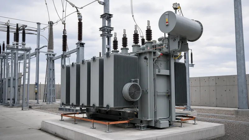
Key takeaways
- An oil filled transformer uses dielectric fluid for simultaneous electrical insulation and convective thermodynamic heat dissipation.
- Mineral oil provides reliable dielectric strength above 30 kV across a standard 2.5 mm gap under IEC 60156 testing conditions.
- Natural and synthetic ester fluids offer K-class fire safety with fire points exceeding 300 degrees Celsius per IEC 61039.
- Sealed-tank designs with corrugated fin walls eliminate conservator breathers, significantly reducing moisture ingress and fluid oxidation.
- Dissolved Gas Analysis according to IEC 60599 serves as the premier predictive maintenance tool for diagnosing incipient thermal and electrical faults.
Quick answer: An oil filled transformer is an electrical power distribution apparatus where the magnetic core and conductive windings are fully submerged in a dielectric fluid that acts as both an electrical insulator and a convective cooling medium. Submerging the active assembly in oil enables higher dielectric breakdown margins, superior heat transfer, and extended operational lifespans compared to dry alternatives.
In high-voltage utility grids, industrial manufacturing facilities, and heavy infrastructure projects, liquid-immersed units handle capacities ranging from small 15 kVA pole installations up to large 100 MVA power substations. Understanding the fluid dynamics, tank construction architectures, and preventative diagnostics of an oil-immersed transformer is essential for project engineers and procurement teams specifying equipment under stringent IEC 60076 and IEEE C57 standards. For details on internal construction, see our guide on transformers internal components.
Operating Principles of an Oil Cooled Transformer
An oil cooled transformer transfers thermal losses generated in the core and windings outward to ambient air through fluid circulation driven by natural convection or forced mechanical pumping.
As electrical current flows through copper or aluminium windings, ohmic losses ($I^2R$) and core hysteresis losses generate significant heat. The dielectric fluid surrounding the active core-and-coil assembly absorbs this thermal energy, expands slightly, drops in relative density, and rises toward the top of the tank. Cooler, denser fluid at the bottom circulates upward to replace it, establishing a natural thermodynamic loop known as thermosiphon circulation.
Cooling performance is categorised according to standard four-letter designations established by IEC 60076-2 and IEEE C57.12.00:
- ONAN (Oil Natural Air Natural): Natural convection circulation of fluid within radiators coupled with natural air convection over cooling fins. Typical for ratings up to 2,500 kVA.
- ONAF (Oil Natural Air Forced): Internal fluid circulates via natural convection, but external fans force high-velocity air across radiator banks, boosting heat rejection by 25% to 33%.
- OFAF (Oil Forced Air Forced): External inline pumps actively circulate oil through heat exchangers while external fans force air through the matrix, applied commonly above 20 MVA.
- ODAF (Oil Directed Air Forced): Fluid is directed via internal baffling directly through the winding conductors for maximum cooling efficiency during sustained grid overloading.
Construction Architectures: Conservator vs Sealed Tank Design
An oil immersed transformer is constructed using either a hermetically sealed tank design or a conservator tank arrangement with an expansion reservoir to accommodate dielectric fluid expansion.
Dielectric fluids have an approximate volumetric expansion coefficient of 0.00075 per degree Celsius. Across an operating temperature swing from -25°C to +95°C, fluid volume fluctuates by roughly 9%. Managing this fluid displacement without exposing the oil to atmospheric oxygen and moisture is critical to preserving dielectric integrity.
Hermetically sealed tanks manage oil expansion through either flexible corrugated steel fin walls (standard in distribution ratings up to 3,150 kVA) or a nitrogen cushion blanket in the head space above the oil (common in industrial IEEE pad-mount designs). By welding the tank completely closed, atmospheric oxygen and ambient humidity are prevented from dissolving into the liquid, eliminating oxidation and the formation of sludge.
Conversely, conservator designs feature a separate expansion drum mounted above the main tank. As oil expands, it enters the conservator, venting displaced air through a dehydrating silica gel breather or an internal rubber diaphragm (air cell). Conservator systems are standard on large power transformers because they allow the main tank to remain completely filled with fluid under positive hydrostatic pressure, enabling the installation of a sensitive mechanical Buchholz relay in the connecting pipework to detect gas accumulation and shock waves from internal flashovers.
Liquid Filled Transformer vs Dry Type: Technical Comparison
Choosing between a liquid filled transformer and a dry-type unit involves balancing initial capital cost, fire risk profile, physical footprint, and installation environment.
While dry-type cast resin units eliminate fluid spillage hazards indoors, oil-immersed variants offer superior energy efficiency, higher overload capacity, better moisture resilience, and lower total lifecycle cost for outdoor substations and heavy industrial plants. The performance trade-offs are detailed in our dry-type transformer guide and summarised below.
| Engineering Parameter | Oil Filled Transformer | Cast Resin Dry Type | Applicable Standard |
|---|---|---|---|
| Cooling Efficiency | High (Thermosiphon fluid circulation) | Moderate (Air duct convection) | IEC 60076-2 |
| Dielectric Breakdown Strength | > 50 kV across 2.5 mm gap | Solid resin casting (> 20 kV/mm) | IEC 60156 / IEC 60076-11 |
| Basic Impulse Insulation Level (BIL) | Higher BIL margins (e.g. 170 kV BIL at 33 kV) | Standard BIL margins (e.g. 125 kV BIL at 33 kV) | IEEE C57.12.00 |
| Service Life Expectancy | 30 to 45 years (with oil conditioning) | 20 to 30 years | CIGRE WG A2 |
| Fire Point | 140°C (Mineral) to >300°C (Ester) | Self-extinguishing resin (Class F1) | IEC 61039 / ISO 2592 |
| Footprint & Weight | Smaller core volume, heavier total mass | Larger enclosure volume, lower mass | Industry average |
| Losses (No-load & Load) | Lower capitalised losses | Slightly higher total losses | EN 50588-1 (Tier 2) |
Dielectric Fluid Types: Mineral Oil, Synthetic Ester, and Natural Ester
A modern oil type transformer can be filled with standard uninhibited mineral oil, synthetic organic esters, or natural seed-based vegetable esters depending on environmental and fire requirements.
Naphthenic mineral insulating oil refined under IEC 60296 has served as the industry baseline for over a century due to its low viscosity (around 11 mm²/s at 40°C), excellent flow dynamics, and cost efficiency. However, its flash point of approximately 140°C classifies it as an O1 fire risk, requiring dedicated containment bunds, separation firewalls, and deluge systems under NFPA 850 or EN 61936-1 guidelines.
To mitigate fire hazards in sensitive locations such as underground vaults, offshore substations, and compact pad-mounted transformers, engineers specify K-class less-flammable fluids defined by IEC 61039:
- Synthetic Esters (Pentaerythritol esters per IEC 61099): Fully synthetic liquids with fire points exceeding 315°C, high moisture tolerance (absorbing over 2,000 ppm water without catastrophic dielectric breakdown), and complete biodegradability per OECD 301.
- Natural Esters (Soya or canola-based per IEC 62770): Vegetable oils offering fire points up to 360°C and carbon-neutral life-cycle credits. They chemically scavenge water from the solid paper insulation via transesterification, decelerating cellulose ageing and extending paper life by a factor of two to three.
Condition Monitoring and Oil Diagnostics
Maintaining high insulation performance in a liquid filled transformer requires systematic condition monitoring using physical sampling, laboratory fluid screening, and dissolved gas analysis.
Dissolved Gas Analysis (DGA) according to IEC 60599 and IEEE C57.104 is the primary diagnostic method for detecting thermal, electrical, and mechanical faults within energised tanks. By extracting fluid samples and testing them via gas chromatography, laboratory technicians quantify specific fault gas concentrations expressed in parts per million (ppm):
- Hydrogen ($H_2$) and Methane ($CH_4$): Indicative of low-energy electrical discharge, partial discharge (corona), or low-temperature localized overheating under 300°C.
- Ethylene ($C_2H_4$): Signifies severe thermal stress in oil or core components exceeding 300°C up to 700°C.
- Acetylene ($C_2H_2$): The definitive marker for high-energy electrical arcing, insulation puncture, or flashover events exceeding 700°C.
- Carbon Monoxide ($CO$) and Carbon Dioxide ($CO_2$): Ratios of $CO_2/CO$ below 3 indicate thermal breakdown and accelerated degradation of solid kraft paper insulation.
Routine fluid maintenance also involves periodic vacuum dehydration and particulate filtration to restore breakdown voltage and dielectric dissipation factors. Refer to our detailed guides on transformer oil testing and the core transformer oil purification guide for field testing thresholds and processing procedures.
Commissioning Procedure for an Oil Filled Transformer
Commissioning an oil filled transformer requires an orderly sequence of electrical, mechanical, and dielectric verification checks prior to initial energisation from the high-voltage supply.
- Visual and Mechanical Integrity Inspection: Verify tank earthing resistance (less than 1.0 ohm), inspect bushings for chipping or oil leaks, check nitrogen blanket pressure (normally 14 to 35 kPa for inert gas systems), and confirm silica gel breather coloration is active.
- Dielectric Liquid Breakdown Screening: Draw bottom-fluid samples according to IEC 60475. Test breakdown voltage per IEC 60156; the dielectric breakdown voltage must exceed 50 kV for systems rated up to 72.5 kV, or 60 kV for extra-high-voltage systems.
- Insulation Resistance and Polarisation Index: Perform a 5 kV DC Megger test between primary-to-secondary, primary-to-ground, and secondary-to-ground windings. Verify that the 10-minute to 1-minute Polarisation Index (PI) ratio is greater than 1.5.
- Winding Resistance and Ratio Verification: Measure DC winding resistance across all taps to verify balanced resistance within 2% across phases. Perform a Turns Ratio (TTR) test across all tap-changer positions, ensuring deviations remain below 0.5% per IEEE C57.12.90.
- Auxiliary and Protection Loop Testing: Trip-test auxiliary trip contacts on the Buchholz relay, pressure relief device (PRD), oil level indicators, and winding temperature indicators (WTI) to confirm interlock isolation of the upstream medium-voltage circuit breaker.
Next steps: specifying and sourcing
When specifying an oil filled transformer for utility, commercial, or industrial applications, compile a comprehensive procurement technical data sheet. Ensure your inquiry specifies the rated capacity (kVA or MVA), primary and secondary nominal voltages, frequency (50 Hz or 60 Hz), vector group (e.g. Dyn11), impedance voltage (%Z), insulation class, altitude and ambient temperature limits, and fluid type (mineral oil versus K-class ester). For customised engineering support, factory-acceptance testing parameters, or project pricing, submit your specification to our engineering team via the transformer quotation portal or visit our direct engineering contact page.
Frequently asked questions
What is an oil filled transformer?
An oil filled transformer is an electrical transformer whose core and windings are submerged in liquid dielectric insulating oil. The fluid provides vital electrical insulation between live conductive components while absorbing and circulating generated heat away from the active core to external tank radiators.
How long does an oil type transformer last?
An oil type transformer typically lasts between 30 and 45 years when operating within rated thermal limits and supported by routine fluid maintenance. Regular dissolved gas analysis, silica gel replacement, and dielectric oil purification prevent premature degradation of the internal kraft paper insulation.
Why is oil used instead of air in large transformers?
Oil provides roughly eight to ten times higher dielectric breakdown strength than ambient air and possesses significantly superior thermal conductivity. Liquid immersion allows much tighter conductor spacing within the core-and-coil assembly, yielding a drastically smaller physical footprint and higher power density than air-cooled units.
What is the difference between mineral oil and ester fluid in transformers?
Mineral oil is a petroleum-derived hydrocarbon with a flash point of 140°C, whereas ester fluid is an organic or synthetic compound with a fire point above 300°C. Esters are classified as less-flammable K-class fluids, provide complete environmental biodegradability, and tolerate much higher moisture concentrations without failing dielectrically.
Can an oil filled transformer be installed indoors?
Yes, an oil filled transformer can be installed indoors provided it complies with local building codes, such as NFPA 70 or EN 61936-1. Standard mineral oil units require dedicated 3-hour fire-rated vaults and containment basins, whereas units using K-class ester fluids can often be installed with standard clearance envelopes.
Tags: oil filled transformer oil type transformer oil immersed transformer liquid filled transformer oil cooled transformer


