Key takeaways
- A step down converter reduces higher distribution or line voltages to lower utilisation levels using either magnetic induction or high-frequency semiconductor switching.
- Magnetic step-down transformers deliver galvanic isolation between primary and secondary circuits in accordance with IEC 60076-1 and IEEE C57.12.00 standards.
- Switch-mode DC-DC buck converters achieve conversion efficiencies exceeding 92% but do not provide physical galvanic isolation unless paired with an isolation stage.
- Sizing an alternating-current step down power converter requires calculating total continuous volt-amperes plus a 25% safety margin under NEC 450 and IEC guidelines.
- A dedicated 110v step down transformer provides safe, isolated secondary circuits for instrumentation, machine control circuits, and portable tools on industrial sites.
Quick answer: A step down converter is an electrical apparatus that reduces an incoming high voltage to a lower, stable output voltage for equipment utilisation. In AC power distribution, this is primarily achieved via electromagnetic transformers that offer complete galvanic isolation, whereas DC systems employ solid-state switched-mode topologies such as buck converters to achieve high efficiency.
Industrial plants, commercial distribution systems, and utilities routinely encounter discrepancies between incoming line levels and the operating voltages of local machinery. High-voltage transmission lines operating at 11 kV, 33 kV, or higher must be reduced systematically before reaching utilisation equipment. Whether stepping down medium voltage across a facility network or supplying 110 V to an automation control rack, engineering teams must specify the correct topology, thermal rating, and impedance. Understanding how magnetic and electronic conversion methods function enables engineers to design reliable, code-compliant distribution networks that mitigate power quality anomalies and thermal failures.
Operating Principles of Voltage Step Down Systems
A voltage step down process relies either on electromagnetic mutual induction or high-frequency pulse-width modulation (PWM) switching to reduce electrical potential. In alternating-current (AC) networks, magnetic induction governs the operation. The primary winding receives an alternating voltage, producing a dynamic magnetic flux within a laminated silicon steel or amorphous core. This flux links with the secondary winding, inducing a secondary electromotive force (EMF) proportional to the turns ratio:
Vp / Vs = Np / Ns = Is / Ip
Here, Vp and Vs represent primary and secondary voltages, Np and Ns denote the winding turns, and Ip and Is represent the respective currents. Because energy is conserved (neglecting core and winding losses), reducing voltage inversely increases current capacity. In large networks, this transition links directly to primary grid infrastructure detailed in our transmission transformer engineering guide.
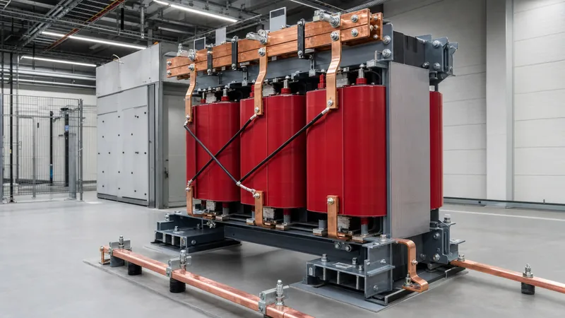
Conversely, solid-state electronic converters use semiconductor switches (MOSFETs or IGBTs) operating at frequencies between 20 kHz and 500 kHz. In a typical DC buck converter, the output voltage is governed by the duty cycle D, where Vout = D × Vin. While switch-mode converters provide compact footprints for low-power DC electronics, large-scale plant distribution requires industrial electromagnetic units such as those found in dry-type transformer installations to withstand transient short-circuit forces and continuous thermal stresses.
Step Down Converter Topologies: Transformers vs Solid-State Units
Selecting between an electromagnetic step-down unit and an electronic power converter depends on the nature of the load, required power rating, and necessity of electrical isolation. Industrial plants rely heavily on two-winding transformers to isolate fault currents, prevent common-mode noise transfer, and protect downstream personnel.
The following table outlines the mechanical and electrical trade-offs across common step-down topologies deployed in commercial and industrial engineering projects:
| Topology | Typical Power Range | Galvanic Isolation | Efficiency (%) | Key Standard | Primary Application |
|---|---|---|---|---|---|
| Two-Winding Dry Transformer | 5 kVA – 30 MVA | Yes (Physical air/resin) | 97.5 – 99.2 | IEC 60076-11 / IEEE C57.12.01 | Factory distribution, LV switchboards, drives |
| Liquid-Immersed Transformer | 50 kVA – 100+ MVA | Yes (Dielectric fluid) | 98.5 – 99.6 | IEC 60076-2 / IEEE C57.12.00 | Substation transformation, outdoor utility grids |
| Autotransformer | 1 kVA – 50 MVA | No (Common winding) | 98.8 – 99.5 | IEC 60076-8 | Interconnecting transmission grids (e.g. 400/230 kV) |
| Solid-State Buck Converter | 1 W – 50 kW | No (Shared ground) | 88.0 – 96.0 | IEC 62477-1 / UL 1741 | DC auxiliary rails, telecommunications, PV DC-DC |
| Isolated DC-DC Converter | 10 W – 250 kW | Yes (HF ferrite core) | 85.0 – 94.0 | IEC 61204-7 / UL 60950 | Battery storage interfaces, EV rapid chargers |
Where total isolation and fault containment are paramount, a magnetic step-down unit remains the mandatory choice. Facilities adopting encapsulated cast-resin designs benefit from low flammability and zero risk of fluid leakage, making them suitable for indoor substations.
Industrial Applications for a Step Down Power Converter
A step down power converter serves critical conversion roles in industrial plants where utility supply voltages exceed the operational threshold of machinery. Typical incoming medium-voltage supplies (such as 11 kV, 22 kV, or 33 kV) must be stepped down to 400 V or 480 V three-phase supplies for motor control centres, industrial chillers, and heavy production lines using robust power transformer hardware.
Secondary distribution applications often involve regional voltage reconciliation. When machinery manufactured for 208 V or 240 V markets is installed in facilities with standard 400 V or 480 V infrastructure, step-down converters ensure equipment operates within design voltage envelopes without overheating internal coils. Similarly, industrial sites rely heavily on a 110v step down transformer to power auxiliary circuits, instrumentation loops, and maintenance hand tools. Supplying 110 V centre-tapped-to-earth (CTE) ensures the maximum shock potential to earth remains at 55 V, complying with stringent occupational health and safety rules on commercial work sites.
For facilities operating multi-voltage equipment arrays, specialized step-down configurations prevent dangerous overvoltages. Detailed design procedures for cross-voltage transformations can be reviewed in our dedicated guide on step down transformer 220V to 110V applications.
How to Size and Select a Step Down Converter
Accurate sizing of a step down converter prevents nuisance tripping, excessive harmonic heating, and insulation breakdown under load. Follow this structured calculation procedure to ensure adequate system capacity:
- Calculate continuous active and apparent load: Sum the continuous loads in amperes (I) and multiply by the line-to-line voltage (V). For three-phase systems, compute total apparent power using S (kVA) = (V × I × √3) / 1000. For single-phase circuits, use S (kVA) = (V × I) / 1000.
- Factor in motor starting inrush currents: Direct-on-line (DOL) electric motors exhibit locked-rotor inrush currents between 600% and 800% of full-load amperes (FLA). Ensure the transformer impedance (%Z) maintains voltage dip within allowable limits (typically ≤10% to 15%) during motor startup cycles.
- Apply safety and expansion margins: Incorporate a mandatory 20% to 25% continuous reserve margin in accordance with NEC Article 450 and IEC 60076 recommendations to accommodate ambient temperature derating and future load additions.
- Assess non-linear harmonic loading: Variable speed drives (VFDs) and switched power supplies generate third, fifth, and seventh-order harmonics. Where non-linear loads exceed 50% of the total rating, specify a K-factor rated unit (such as K-4 or K-13) or select an oversized dry-type unit to mitigate eddy-current winding losses.
Engineers can verify complex load profiles and multi-tier diversity factors by referencing our comprehensive transformer sizing calculator guide.
Installation, Protection, and Compliance Standards
Installing a step down converter requires strict adherence to international safety codes governing thermal dissipation, overcurrent protection, and grounding integrity. Magnetic converters generate copper (I2R) and iron core losses that manifest as heat. Engineers must confirm that indoor transformer rooms maintain sufficient natural convection or forced-air cooling in compliance with IEC 60076-2 thermal rise standards (e.g., 100 K rise over a 40°C ambient for Class F insulation).
Overcurrent protection must be calibrated on both primary and secondary windings. Because closing the primary circuit breaker initiates magnetic core inrush—which can reach 10 to 12 times full-load current for several cycles—the primary protective relay or fuse must incorporate an intentional time-delay (inverse-time characteristic) to avoid nuisance trips, per IEEE C37.91 recommendations.
Proper earthing (grounding) represents the final compliance check. For derived secondary circuits, such as an internal 110 V or 400 V star network, the neutral point must be solidly bonded to the main earthing terminal (MET) under TN-S earthing protocols. This low-impedance path ensures instantaneous disconnection of circuit breakers during line-to-earth fault events.
Next steps: specifying and sourcing
When preparing an inquiry or technical specification for a step down converter, compile your exact primary and secondary voltages, system frequency (50 Hz or 60 Hz), phase count, required kVA capacity, vector group (e.g., Dyn11), and installation environment (indoor IP20 or outdoor weatherproof enclosure). For high-performance distribution assets, explore our advanced power transformer solutions and factory-tested dry-type transformers designed for demanding continuous industrial service. Submit your single-line diagram and load schedule directly to our engineering specialists at our transformer quotation portal to receive detailed general arrangement drawings, guaranteed loss figures, and comprehensive manufacturing lead times.
Frequently asked questions
What is a step down converter?
A step down converter is an electrical device that reduces a higher input voltage to a lower, stable output voltage. In AC distribution, this is achieved using electromagnetic transformers with fewer secondary turns than primary turns. In DC circuits, it is accomplished using high-frequency semiconductor switching circuits such as buck converters.
What is the difference between a step down converter and a step down transformer?
A step down transformer is an electromagnetic device that converts AC voltage levels while providing physical galvanic isolation between circuits. A step down converter is a broader term that encompasses both magnetic AC transformers and solid-state electronic circuits (such as DC-DC buck regulators) that decrease voltage levels without magnetic coupling.
Can an AC step down converter run in reverse as a step up converter?
Yes, standard two-winding electromagnetic transformers are bidirectional and can function in reverse as step-up devices if energised from the low-voltage winding. However, tap ranges, inrush currents, and winding compensation must be reviewed by an engineer because factory tap changers and insulation structures are optimised for designated primary inputs.
Why do industrial facilities use a 110v step down transformer?
Industrial facilities utilise 110V step down transformers primarily for personnel safety and code compliance on construction and maintenance sites. By centre-tapping the 110V secondary winding to earth, the maximum fault potential between any live conductor and earth is restricted to 55V AC, substantially mitigating electrocution risks.
How do you calculate the required kVA for a step down power converter?
To calculate required kVA, multiply the load current by the operating voltage (and by 1.732 for three-phase systems), divide by 1,000, and add a 20% to 25% safety margin. For example, a 400V three-phase load drawing 100A requires (400 x 100 x 1.732) / 1000 = 69.3 kVA, requiring an 80 kVA or 100 kVA standard transformer.
Tags: step down converter voltage step down step down power converter 110v step down transformer power transformers


