Key takeaways
- A step up transformer diagram illustrates a lower-voltage primary winding with fewer turns magnetically coupled across a laminated core to a higher-voltage secondary winding with more turns.
- Terminal markings adhere strictly to international conventions: IEC 60076-1 designates higher-voltage terminals with upper-case Latin letters (1U, 1V, 1W) and lower-voltage with (2U, 2V, 2W), while IEEE C57.12.00 employs H for high-voltage and X for low-voltage bushings.
- The voltage transformation ratio equates directly to the winding turns ratio (Vs/Vp = Ns/Np) while the operating line currents vary inversely (Ip/Is = Vs/Vp), maintaining conservation of apparent power less internal losses.
- Loop-feed distribution arrangements on step-up generation units require dual-bushing primary/secondary configurations to daisy-chain multiple assets along a single medium-voltage collector feeder.
- Verification of transformer vector groups such as Dyn11 or YNd11 must be confirmed via phase-angle displacement and turns-ratio testing in accordance with IEC 60076-1 clause 11.3 before site energisation.
Quick answer: A step up transformer diagram is an engineering schematic that illustrates the electrical connections, magnetic core coupling, vector groups, and relative turns ratio where the secondary winding has a higher turn count and delivers a higher output voltage than the input voltage supplied to the primary winding.
In modern industrial systems, power generation stations, and renewable energy collector circuits, stepping up generation voltages to medium-voltage (MV) or high-voltage (HV) transmission thresholds is essential to minimise line losses ($I^2R$). Understanding how to interpret and construct a comprehensive step up transformer diagram enables protection engineers, substation designers, and installation contractors to select correct bushing terminations, specify proper switchgear ratings, and ensure fault coordination across distribution networks. Whether integrating solar inverters at 800 V or wind turbine generators at 690 V into a 33 kV collector ring, accurate schematic interpretation prevents severe phase mismatch and insulation breakdown.
Step Up Transformer Definition and Operating Principles
A precise step up transformer definition states that it is a static electrical machine that converts alternating current (AC) electrical energy from a lower potential to a significantly higher potential at identical frequency through mutual electromagnetic induction. To properly explain step up transformer behaviour, one must refer to Faraday’s law of electromagnetic induction and Ampere's circuital law.
When an alternating voltage $V_p$ energises the primary winding, it drives an alternating magnetising current that establishes a time-varying magnetic flux $\Phi$ within the high-permeability silicon steel core. In accordance with Faraday's law, this alternating flux links both windings, inducing an electromotive force (EMF) across each coil proportional to its physical number of turns. For a detailed review of winding design mechanics, consult our guide on transformer primary and secondary windings. The fundamental turns ratio equation is defined as:
$$\frac{V_s}{V_p} = \frac{N_s}{N_p} = \frac{I_p}{I_s}$$
Where $V_s$ and $V_p$ are secondary and primary voltages, $N_s$ and $N_p$ represent the secondary and primary winding turns, and $I_p$ and $I_s$ represent primary and secondary currents. In any step up transformer diagram, $N_s$ exceeds $N_p$. Because total apparent power ($S = \sqrt{3} \cdot V \cdot I$) is conserved across an ideal transformer, an increase in voltage on the secondary side forces a proportional reduction in secondary current, allowing power transmission over long distances using substantially smaller conductor cross-sections.
Anatomy of a Step Up Transformer Diagram: Symbols and Markings
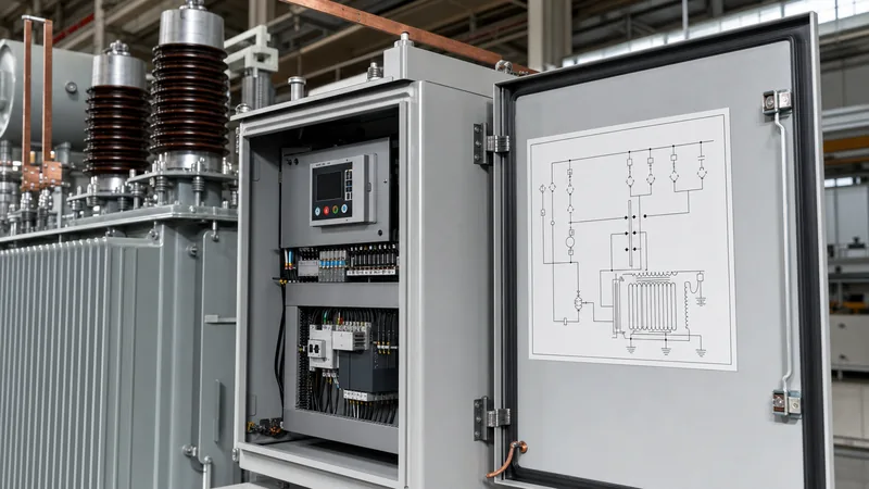
A standard step up transformer diagram incorporates specific international drafting symbols to communicate winding orientation, terminal identification, core geometry, and earthing arrangements. Standard industrial schematics conform either to IEC 60617 graphical symbols or IEEE Std 315/ANSI standards.
When reading a step up transformer diagram, several core structural components must be identified:
- Primary Windings (Low Voltage): Drawn with fewer winding loops, representing the input side fed from the generator or inverter stage. Per IEEE C57.12.00 Table 5, LV terminals are designated as X1, X2, X3 (and X0 if neutral exists). In IEC schematics, LV terminals are denoted as 2U, 2V, 2W, and 2N.
- Secondary Windings (High Voltage): Rendered with a visibly higher density of winding loops. IEEE designations assign H1, H2, H3 (and H0) to this side, while IEC standards label these terminals as 1U, 1V, 1W, and 1N per IEC 60076-1 clause 6.
- Magnetic Core: Represented by parallel solid lines drawn between the primary and secondary coils, indicating a laminated magnetic core (grain-oriented electrical steel) that provides a closed path for mutual flux.
- Polarity / Dot Convention: Instantaneous polarity dots mark terminals that share the same instantaneous relative voltage polarity. Current entering a dotted primary terminal induces a current exiting the corresponding dotted secondary terminal.
- Vector Group Representation: A symbolic alphanumeric code (such as Dyn11 or YNd1) placed adjacent to the coil schematics to indicate the phase displacement between HV and LV line terminals.
For large generation stations requiring robust grid interconnection, these drawings clarify how intermediate apparatus such as an oil-immersed transformer or a heavy-duty power transformer interfaces with protective switchgear.
Vector Diagrams and Phase Displacement for Three-Phase Step-Up Units
Vector groups define the winding interconnections and the angular phase displacement between the primary and secondary line voltage waveforms. In any three-phase step up transformer diagram, vector group representation dictates system grounding, fault current magnitude, and third-harmonic flux suppression.
In renewable generation and industrial co-generation plants, two prominent vector groups appear consistently on single-line and connection schematics:
- Dyn11 Configuration: The primary winding is delta-connected (D), while the secondary winding is star-connected (y) with an accessible neutral point (n). The numeral 11 represents a 30-degree phase lead of the secondary line voltage relative to the primary line voltage (corresponding to the 11 o'clock position on a clock face). The delta primary traps third-harmonic currents, preventing harmonic injection upstream, while the star secondary provides a solidly grounded neutral for distribution networks.
- YNd1 Configuration: The primary is star-connected with neutral (YN) and the secondary is delta-connected (d), introducing a 30-degree phase lag (1 o'clock position). This arrangement is frequently deployed when stepping up medium-voltage utility power into isolated, ungrounded industrial networks.
- Yy0 Configuration: Star-star configuration with zero phase displacement. While straightforward on a schematic, Yy0 requires a tertiary delta winding to circulate harmonic currents and stabilise the neutral potential under unbalanced load conditions.
Understanding these vector configurations is critical when designing systems governed by our medium voltage transformer guide, ensuring that synchronising relays do not trip on false phase differentials.
Worked Engineering Calculation: Sizing and Turns Ratio on a Step-Up Unit
Calculating the precise turns ratio, line currents, and equivalent impedance determines the operational parameters presented on a manufacturing step up transformer diagram. Consider a grid-tied utility solar installation where a step-up distribution unit links an inverter output station to a 33 kV collector network.
Design Parameters:
- Rated apparent power ($S_n$): 2,500 kVA (2.5 MVA)
- Rated primary voltage line-to-line ($V_{p,LL}$): 690 V (Delta connection)
- Rated secondary voltage line-to-line ($V_{s,LL}$): 33,000 V (Star connection, neutral earthed)
- Rated frequency ($f$): 50 Hz
- Impedance voltage ($e_z$ / %Z): 6.0%
- Vector group: Dyn11
Step 1: Calculate Primary and Secondary Rated Line Currents
Using the three-phase apparent power formula $I = \frac{S}{\sqrt{3} \cdot V_{LL}}$:
$$I_p = \frac{2,500,000 \text{ VA}}{\sqrt{3} \cdot 690 \text{ V}} = \frac{2,500,000}{1,195.12} = 2,091.84 \text{ A}$$
$$I_s = \frac{2,500,000 \text{ VA}}{\sqrt{3} \cdot 33,000 \text{ V}} = \frac{2,500,000}{57,157.68} = 43.74 \text{ A}$$
Step 2: Calculate Phase Voltages and Turns Ratio
Because the primary is delta-connected, the primary phase voltage equals the line-to-line voltage: $V_{p,phase} = 690 \text{ V}$.
Because the secondary is star-connected, the secondary phase voltage is derived as:
$$V_{s,phase} = \frac{V_{s,LL}}{\sqrt{3}} = \frac{33,000 \text{ V}}{\sqrt{3}} = 19,052.56 \text{ V}$$
The physical turns ratio ($N_s / N_p$) per phase is calculated using phase voltages:
$$\text{Turns Ratio} = \frac{N_s}{N_p} = \frac{V_{s,phase}}{V_{p,phase}} = \frac{19,052.56 \text{ V}}{690 \text{ V}} = 27.61:1$$
Consequently, the high-voltage secondary winding requires precisely 27.61 turns for every single turn on the low-voltage primary winding. The schematic must state these nominal phase voltages alongside terminal designations to avoid incorrect field tapping.
Loop-Feed Distribution Schemes for Step-Up Configurations
In renewable collection arrays and modular industrial complexes, transformers are frequently wired in loop-feed configurations rather than traditional radial dead-end topologies. A loop-feed schematic illustrates incoming and outgoing high-voltage cables connected to parallel bushing terminations, enabling network sectionalising and continuous service during line maintenance.
To evaluate feed configurations for generation step-up layouts, consult our foundational article on radial feed vs loop feed systems. In a typical loop-feed step-up arrangement, an oil-immersed pad-mounted transformer features six MV bushings (two per phase: H1A/H1B, H2A/H2B, H3A/H3B) alongside a multi-position load-break switch. This architecture allows the step-up transformer to feed its generated capacity onto a common MV ring collector while passing the ring feeder current through to downstream units.
| Engineering Criteria | Radial Step-Up Wiring | Loop-Feed Step-Up Wiring |
|---|---|---|
| Bushing Quantity (HV Side) | 3 Bushings (H1, H2, H3) | 6 Bushings (H1A/B, H2A/B, H3A/B) |
| Internal Switching Options | None or single On/Off switch | 4-position switch (Loop A, Loop B, Loop A&B, Off) |
| Network Reliability | Single point of failure; cable fault drops entire unit | Fault isolation allows backfeeding from opposite ring terminal |
| Cabling Complexity | Single three-core or single-phase runs per phase | Dual three-core or dual single conductors per phase |
| Capital Cost | Lower initial procurement cost | 5% to 15% higher equipment expenditure |
| Application Suitability | Isolated generation plants, dedicated export feeders | Utility-scale solar farms, wind plant collector rings |
When reviewing collector designs in grid integration of renewable energy sources, the loop-feed step up transformer diagram clarifies how protective relays locate and isolate ground faults without shutting down an entire generation cluster.
Step-Up Transformer Inspection and Schematic Verification Checklist
A site acceptance inspection requires physical verification against the approved manufacturer schematic diagram. Technicians must methodically audit winding polarity, terminal markings, and insulation values prior to closing circuit breakers.
- Nameplate and Diagram Comparison: Verify that the installed unit’s nameplate matches the engineering single-line diagram, confirming rated kVA, primary/secondary voltages, tap-changer steps (e.g., ±2 × 2.5%), and vector group designation (IEC 60076-1 clause 5.4).
- Bushing Orientation and Phase Labelling: Inspect terminal labels (1U, 1V, 1W vs 2U, 2V, 2W or standard IEEE high-voltage vs low-voltage designations). Ensure high-voltage surge arresters are located adjacent to the HV bushings as documented in the arrangement drawing.
- Voltage Turns Ratio (VTR) Measurement: Apply test voltages across each phase to verify calculated turns ratios across all tap positions in accordance with IEC 60076-1 clause 11.3; variance must not exceed ±0.5% of declared values.
- Vector Group and Phase Displacement Verification: Perform the standard bridge connection test (linking terminal 1U to 2U) and measure inter-terminal voltages across remaining phases to confirm phase angle rotation matches Dyn11 or designated clock scheme.
- Insulation Resistance and Polarization Index: Execute Megohmmeter tests between HV-to-LV windings, HV-to-ground, and LV-to-ground using IEEE C57.152 recommendations (typically 2.5 kV or 5 kV DC injection).
- Internal Auxiliary and Protection Wiring: Confirm CT wiring diagrams, winding temperature indicators (WTI), liquid temperature indicators (OTI), and Buchholz gas relay trip circuits correspond to the electrical control schematic.
Next steps: specifying and sourcing
When preparing an RFQ for medium- or high-voltage step-up distribution equipment, provide your prospective manufacturer with a complete single-line diagram, required primary and secondary voltages, BIL ratings, vector group specifications, short-circuit current limitations, and site environmental conditions. Explore our heavy-duty power transformer series, high-efficiency oil-immersed distribution units, or utility-grade pad-mounted transformers. For bespoke engineered schematics, custom vector configurations, or immediate project tenders, contact our applications engineering team through our technical contact page or submit your parameters directly via our transformer quotation portal.
Frequently asked questions
What is the main difference between a step up and step down transformer diagram?
A step up transformer diagram shows fewer winding turns on the low-voltage primary input and more winding turns on the high-voltage secondary output. Conversely, a step down transformer diagram illustrates the reverse arrangement, with higher turns on the primary supply and fewer turns on the secondary distribution side.
Can a step up transformer be connected in reverse to step down voltage?
Yes, standard transformers are bidirectional machines, meaning supplying rated voltage to the designated secondary winding will step down voltage at the primary terminals. However, winding insulation gradients, tap-changer locations, and internal core compensation are factory-optimised for specific directional power flow, so reversing duty must be validated with the manufacturer.
Why do step up transformer diagrams frequently specify delta-wye (Dyn11) connections?
Delta-wye (Dyn11) arrangements are widely specified because the low-voltage delta winding traps third-harmonic zero-sequence currents generated by upstream loads or inverters. Simultaneously, the star secondary provides a solidly grounded neutral on the high-voltage transmission side, facilitating effective ground fault protection and balanced line-to-neutral voltages.
What do the H and X markings indicate on transformer schematics?
Under IEEE and ANSI standards, 'H' designations represent the high-voltage windings and bushings, while 'X' designations denote the low-voltage windings. On a step-up transformer diagram, the input power enters through the X terminals and the elevated output voltage departs via the H terminals.
How is the turns ratio calculated on a step-up unit?
The turns ratio is calculated by dividing the secondary phase voltage by the primary phase voltage (Ns / Np = Vs,phase / Vp,phase). In polyphase transformers, line-to-line voltages must first be converted into per-phase winding voltages based on whether the windings are configured in delta or star.
Tags: step up transformer diagram step up transformer definition explain step up transformer transformer schematics loop feed distribution


