Key takeaways
- A substation transformer transforms transmission or sub-transmission voltages down to medium-voltage distribution levels or vice versa, typically operating from 5 MVA to over 100 MVA.
- Cooling classifications defined by IEC 60076 and IEEE C57.12 determine continuous thermal capacity across natural convection (ONAN) and forced auxiliary stages (ONAF/OFAF).
- Percentage impedance (%Z) directly governs short-circuit fault levels and voltage regulation, typically engineered between 7% and 12% for medium-power units.
- Transformer sub station layouts require compliant physical containment bunds capable of holding 100% of the dielectric fluid plus rainwater allowances per IEC 61936-1 and NFPA 850.
- Comprehensive asset protection relies on differential relaying (ANSI 87T), Buchholz gas detection relays, and thermal monitoring devices for both oil and winding hot-spots.
Quick answer: A substation transformer is a heavy-duty electrical apparatus that steps transmission voltages down to distribution levels, or steps generation voltages up for transmission, typically operating at ratings from 5 MVA to beyond 100 MVA under continuous utility or industrial duty.
In electrical utility networks and heavy industrial facilities, the substation transformer represents the primary link between high-voltage transmission grids and regional power distribution. Whether installed as a primary bulk-power unit or an intermediate step-down device within an industrial network, an electrical substation transformer must withstand lightning impulses, switching transients, continuous thermal stress, and through-fault mechanical forces. Specifying the correct transformer sub station equipment requires balancing dielectric integrity, loss evaluation formulas, impedance tolerances, and protection coordination. For engineers planning full grid infrastructure, comparing substation layouts with our transmission transformer engineering guide provides essential context on grid-level voltage staging.
What Is a Substation Transformer and How Does It Work?
A substation transformer is a stationary electromagnetic device that transfers electrical energy between circuits at differing voltage levels through mutual induction, providing critical voltage conversion and galvanic isolation at network switching nodes.
Inside the sealed or conservator-type steel tank, magnetic flux circulating through a laminated silicon steel core links the primary high-voltage (HV) and secondary low-voltage (LV) windings. The voltage transformation ratio corresponds directly to the winding turn ratio according to Faraday's law of induction:
V1 / V2 = N1 / N2 = I2 / I1
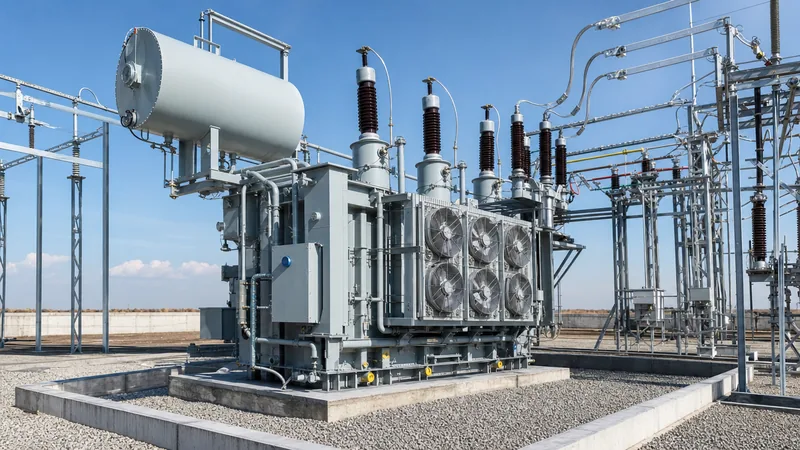
Substation units differ from light pole-mounted or small commercial transformers by virtue of their structural scale, insulation margins, cooling architecture, and instrumentation. A substation power transformer incorporates on-load tap changers (OLTC) or de-energised tap changers (DETC), oil preservation systems, continuous gas monitoring provisions, and reinforced mechanical bracing capable of withstanding electromagnetic forces exceeding several hundred kilonewtons during short-circuit faults. You can examine detailed internal core structures in our analysis of high-voltage transformer engineering.
Classifications of Electrical Substation Transformers
Electrical substation transformers are categorised primarily by system voltage class, power rating, dielectric cooling medium, and operational topology within the network.
- Transmission and Sub-Transmission Units: These primary units operate at voltages from 69 kV to 230 kV and above, stepping power down to regional sub-transmission levels (typically 33 kV, 22 kV, or 11 kV). Capacities range from 20 MVA to upwards of 120 MVA.
- Distribution Substation Transformers: Stationed at the perimeter of urban or industrial load centres, a distribution sub transformer steps medium voltages down to local feeding voltages (such as 11 kV down to 3.3 kV or 400 V). Ratings typically sit between 1 MVA and 20 MVA.
- Unit Auxiliary Transformers (UAT): Stationed at generation facilities and major industrial substations, these supply auxiliary plant power, stepping down generation voltages (e.g., 15 kV to 24 kV) to medium-voltage motor busbars (6.6 kV or 3.3 kV).
- Collector Substation Transformers: Purpose-engineered for renewable wind and solar farms, these units step up medium-voltage collector feeder circuits (typically 33 kV or 34.5 kV) to grid-interconnect levels (110 kV to 220 kV), requiring robust design against repetitive harmonic loading and fluctuating solar cycles.
For modular and site-constrained installations, specifiers often choose prefabricated compact substations that integrate the step-down unit, switchgear, and low-voltage panels within an engineered outdoor housing.
Key Engineering Specifications and Performance Parameters
Specifying a substation power transformer requires rigorous definition of electrical, thermal, and mechanical parameters governed by IEC 60076 or IEEE C57.12 standards.
The unit's percentage impedance (%Z) defines the internal voltage drop under full load and establishes the maximum prospective symmetrical short-circuit current (Isc = Irated / %Z). Correct impedance selection balances fault currents against voltage regulation: excessively low impedance subjects downstream switchgear to catastrophic fault duties, while elevated impedance causes unmanageable voltage drops during motor starting. Engineers calculating these loads should consult our transformer sizing engineering guide to verify rating margins.
| Parameter | Standard Range | Relevant Standard | Engineering Impact |
|---|---|---|---|
| Rated Power (MVA) | 5 MVA to 100+ MVA | IEC 60076-1 / IEEE C57.12.00 | Defines continuous MVA capability at rated temperature rise |
| HV / LV Voltages | 33 kV up to 230 kV / 3.3 kV to 33 kV | IEC 60038 | Dictates winding turns ratio and bushing dielectric insulation |
| BIL Rating (kV Peak) | 170 kV to 1050 kV | IEC 60076-3 / IEEE C57.98 | Defines withstand against lightning and switching surges |
| Percentage Impedance (%Z) | 7.0% to 12.5% | IEC 60076-1 | Controls prospective short-circuit currents and voltage drop |
| Cooling Classes | ONAN / ONAF / OFAF | IEC 60076-2 | Determines base rating versus forced-air/forced-oil operational stages |
| Vector Group | Dyn11, YNd11, YNyn0 | IEC 60076-1 | Establishes phase displacement and neutral grounding options |
| Tap Changer Range | ±10% to ±16% in 1.25% steps | IEC 60214-1 | Regulates busbar voltage under fluctuating utility grid conditions |
Cooling Classifications and Thermal Limits
Cooling designations dictate how effectively a substation transformer evacuates core hysteresis and winding copper losses to avoid thermal degradation of cellulose insulation paper.
Modern oil-immersed electrical substation transformers follow four-letter cooling designations defined under IEC 60076-2 and IEEE C57.12.00:
- ONAN (Oil Natural, Air Natural): Base cooling rating where hot oil circulates by thermosiphon convection through radiator banks cooled by natural ambient air currents.
- ONAF (Oil Natural, Air Forced): Motor-driven cooling fans activate when winding temperatures reach preset thresholds (e.g., 65°C to 75°C), increasing thermal dissipation and raising output capacity by 25% to 33% above the ONAN rating.
- OFAF / ODAF (Oil Forced, Air Forced / Directed): Circulating pumps force dielectric oil through heat exchangers or directed winding ducts, unlocking high peak ratings for heavy industrial and transmission duties.
For urban locations or underground stations where fire safety codes strictly restrict liquid oil volume, specifying heavy-duty cast-resin dry units through our dry-type transformer options eliminates liquid flammable hazards entirely.
Siting, Civil Foundations, and Installation in a Transformer Sub Station
Civil and physical installation of a transformer sub station mandates compliance with structural load ratings, fire separation distances, and environmental containment regulations.
Per standards such as IEC 61936-1 and NFPA 850, outdoor oil-filled transformers must maintain specified clear spaces from buildings and adjacent units, or incorporate fire-rated blast partition walls. The installation procedure follows a strict sequence:
- Foundation and Retention Bund Construction: Cast a reinforced concrete pad sized to the unit's operating weight (often 30 to 150 metric tonnes). The foundation must include an integrated retention basin capable of capturing 100% of the transformer dielectric fluid volume plus a 24-hour storm precipitation allowance, routing effluent through a flame-trap rock layer or oil-water separator.
- Rigging and Core Placement: Transport the transformer main tank to site with core and windings secured. Carefully jack and skate or crane the unit onto its anti-vibration pads or foundation mounting rails.
- Accessory and Bushing Dressing: Erect the conservator tank, radiator panels, pipework, and high-voltage porcelain or composite condenser bushings under dry weather conditions to prevent moisture ingress into the insulating fluid.
- Vacuum Treatment and Fluid Filling: Evacuate the tank under deep vacuum (typically below 1 mbar / 0.75 Torr) to remove trapped gas voids, followed by de-aerated, dry dielectric oil filling per strict dielectric breakdown voltage benchmarks (>60 kV across 2.5 mm gap).
- Secondary Cabling and Earth Mat Bonding: Connect low-voltage neutral and tank grounding pads to the station earth grid with copper conductors sized for maximum system ground-fault current, ensuring low earth resistance (typically <1.0 Ohm).
Protection and Monitoring Schemes for Substation Power Transformers
Protection engineering for a substation power transformer combines electrical unit protection relays with mechanical and thermodynamic fluid sensors to isolate internal faults within milliseconds.
Because electrical substation transformers represent high-capital assets, protective architectures use multiple overlapping zones. Primary electrical protection includes:
- Differential Protection (ANSI 87T): The primary defence against phase-to-phase and phase-to-ground winding faults. It compares current entering and exiting each phase, incorporating second-harmonic restraint (typically set at 15% to 20%) to avoid tripping during magnetising inrush current surges.
- Restricted Earth Fault (ANSI 64REF): High-impedance or low-impedance protection engineered to detect internal winding ground faults located near the neutral star point.
- Overcurrent and Earth Fault (ANSI 50/51, 51N): Time-graded backup protection for system-level through-faults and external busbar short circuits.
Complementary mechanical protection relies on the Buchholz relay (ANSI 63) installed in the pipe between tank and conservator, tripping the incoming circuit breaker upon detecting gas buildup or oil surges. Pressure relief devices (PRD) exhaust abrupt hydraulic pressure waves caused by heavy arcing. To configure comprehensive relay schematics, study our specialised substation transformer protection engineering guide.
Testing, Commissioning, and Asset Maintenance Protocols
Commissioning and routine maintenance of electrical substation transformers ensure that dielectric, mechanical, and thermal parameters remain well within factory design limits over decades of operation.
Field validation protocols follow IEC 60076-1 and IEEE C57.152 recommendations. Routine operational testing includes:
- Dissolved Gas Analysis (DGA): Evaluates concentrations of key fault gases (hydrogen, methane, acetylene, ethylene, ethane) dissolved in oil via gas chromatography. Detecting acetylene (C2H2) above 1–2 ppm provides early warning of high-energy electrical arcing within core or tap changer compartments.
- Insulation Resistance and Polarisation Index (PI): Measured at 2.5 kV or 5 kV DC between windings and ground. A 10-minute to 1-minute PI ratio above 2.0 indicates dry, uncontaminated insulation paper.
- Dielectric Dissipation Factor (Tan Delta / Power Factor): Quantifies dielectric losses in bulk insulation and high-voltage bushings; values exceeding 0.5% at 20°C signal thermal degradation or moisture contamination.
- Sweep Frequency Response Analysis (SFRA): Compares frequency-response transfer functions against factory baselines to detect sub-millimetre physical displacement of windings following severe through-fault forces.
Next steps: specifying and sourcing
When specifying a substation transformer for utility, industrial, or renewable generation projects, your engineering tender must provide complete system parameters: rated power capacity (MVA), primary and secondary nominal voltages, BIL requirements, tap changer configuration (OLTC or DETC), maximum sound power levels, and ambient site extremes. Explore our engineered line of heavy-duty liquid-immersed power transformers and integrated transformer substation units designed in full compliance with IEC and IEEE standards. Submit your single-line diagrams, loss capitalisation figures, and specification schedules via our transformer quotation portal to receive tailored engineering reviews, outline drawings, and commercial proposals from our design team.
Frequently asked questions
What is the primary function of a substation transformer?
A substation transformer's primary function is to step voltage levels up or down between transmission, sub-transmission, and distribution networks while providing galvanic isolation. This enables high-efficiency, long-distance power transfer and delivers manageable, lower voltage levels to distribution busbars and downstream industrial consumers.
What is the difference between a substation transformer and a distribution transformer?
Substation transformers handle bulk power (typically 5 MVA to 100+ MVA) at higher voltage classes (33 kV to 230 kV) and incorporate advanced cooling, tap-changing, and monitoring equipment. In contrast, distribution transformers are smaller units (typically 16 kVA to 2,500 kVA) that step medium voltage directly down to customer utilisation voltages like 400 V or 120/240 V.
Why is percentage impedance critical in a substation power transformer?
Percentage impedance determines the voltage regulation across the transformer under load and directly limits the maximum prospective short-circuit fault current. Sizing impedance appropriately (usually between 7% and 12.5%) prevents excessive downstream fault currents that would exceed switchgear breaking capacity, while ensuring bus voltage stability.
What does ONAN / ONAF cooling mean on an electrical substation transformer?
ONAN/ONAF indicates a dual-stage cooling design: Oil Natural Air Natural and Oil Natural Air Forced. The unit operates safely under base loads using natural oil thermosiphon convection and radiator air currents (ONAN), but activates electric cooling fans to dissipate more heat and raise MVA capacity during higher load conditions (ONAF).
How often should substation transformer oil be tested?
Dielectric oil in critical substation transformers should undergo Dissolved Gas Analysis (DGA) and moisture-breakdown testing at least once annually under normal conditions, or continuously via online multi-gas monitors. Higher-risk or heavily loaded industrial units often require biannual fluid testing to catch developing thermal or electrical faults early.
What is the role of an on-load tap changer (OLTC) in a transformer sub station?
An on-load tap changer dynamically varies the transformer winding turns ratio while under electrical load, compensating for system-wide grid voltage fluctuations. This regulates the secondary busbar voltage within statutory tolerances without requiring supply interruptions to downstream customers.
Tags: substation transformer substation power transformer transformer sub station sub transformer electrical substation transformers


