Key takeaways
- An online transformer monitoring system continuously tracks critical health indicators including dissolved gases, moisture, winding hot spots, and bushing power factor to prevent catastrophic failures.
- Dynamic thermal modelling per IEC 60076-7 enables real-time calculation of winding hot-spot temperature and relative rate of thermal ageing under variable loading.
- Continuous Dissolved Gas Analysis (DGA) detects incipient electrical and thermal faults months before standard Buchholz gas relays trigger.
- Integrated bushing monitoring measures changes in capacitance (C1) and dissipation factor (tan delta) to identify moisture ingress and dielectric degradation under line voltage.
- Implementing transformers with digital monitoring protocols like IEC 61850-8-1 reduces maintenance expenditure by shifting substation assets from calendar-based to condition-based interventions.
Quick answer: Transformer monitoring is the continuous, real-time tracking of electrical, thermal, chemical, and mechanical parameters of a transformer to identify incipient faults, optimise dynamic loading, and prevent catastrophic substation outages. Modern systems integrate multi-gas dissolved gas analysis, fibre-optic temperature probes, bushing power factor sensors, and intelligent electronic devices (IEDs) communicating via IEC 61850.
High-voltage power transformers represent the single most critical asset in transmission and distribution networks, often accounting for more than 50% of total substation capital expenditure. Unplanned outages resulting from internal arc flashovers, dielectric breakdown, or mechanical collapse of the winding structure inflict severe financial penalties, extensive downstream interruption, and catastrophic environmental contamination. Historical utility operational data indicates that over 70% of high-impact transformer failures originate from slowly evolving degradation mechanisms within the insulation system, high-voltage bushings, or on-load tap changers (OLTC). By moving beyond periodic manual testing to automated transformer monitoring, asset managers capture subtle deviations in asset condition early, extending operating lifespans past their design thresholds while safely operating closer to thermal boundaries.
Architecture of a Transformer Monitoring System
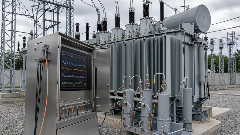
A transformer monitoring system combines edge-mounted physical sensors, data acquisition nodes, local digital processing units, and high-level analytical interfaces into a unified diagnostic architecture. Rather than relying on isolated instruments, modern installations centralise telemetry from every critical sub-assembly to build a continuous asset health index.
At the physical sensor layer, hardware directly interfaces with the dielectric liquid, winding structure, and primary terminals. These include resistive temperature detectors (Pt100 RTDs), fibre-optic probes, current transformers, capacitive taps, and electrochemical or photo-acoustic gas sensors. Signals pass directly or via local junction boxes into substation-hardened IEDs designed according to IEC 60255 environmental standards, ensuring electromagnetic compatibility (EMC) against high-voltage switching surges and transient ground potential rises.
The supervisory layer consolidates these distributed data streams. An on-tank hub or control-room server hosts algorithmic engines that execute real-time thermal models, gas-ratio diagnostics, and bushing trending. Standardised communication links transfer processed telemetry over substation local area networks. Most industrial and utility systems adopt IEC 61850-8-1 Manufacturing Message Specification (MMS) or Modbus TCP/IP over redundant fibre-optic Ethernet rings, delivering live data to an enterprise transformer monitoring dashboard alongside standard SCADA alarms. This architecture allows plant engineers to assess fleet health remotely and schedule targeted interventions without de-energising active power transformer assets.
Online Transformer Monitoring System: Core Monitored Parameters
An online transformer monitoring system tracks chemical, thermal, electrical, and mechanical indicators to provide total asset visibility under variable system conditions.
Different sub-assemblies deteriorate under distinct stress vectors, requiring dedicated sensor technologies:
- Dissolved Gas Analysis (DGA): Continuous extraction and measurement of key fault gases dissolved in the dielectric fluid, including hydrogen (H2), methane (CH4), acetylene (C2H2), ethylene (C2H4), ethane (C2H6), carbon monoxide (CO), and carbon dioxide (CO2).
- Moisture in Oil: Solid-state capacitive thin-film polymer probes installed in active oil flow paths measure water activity (aw) and calculate moisture concentration in parts per million (ppm), identifying insulation wetness and bubble-formation hazards.
- Temperature Profiles: Top-oil, bottom-oil, core, and direct winding temperatures measured through Pt100 elements and gallium arsenide (GaAs) fibre-optic sensors embedded between winding conductors during factory assembly.
- Bushing Health: Continuous measurement of leakage currents via the capacitive test tap (C1) of high-voltage condenser bushings, evaluating changes in capacitance and dissipation factor (tan delta / power factor). Read our detailed transformer bushing engineering guide for further analysis on bushing degradation physics.
- On-Load Tap Changer (OLTC) Performance: Dynamic motor drive current profiling, contact wear calculation based on interrupted current (I2t), vibro-acoustic signature analysis, and differential oil temperature monitoring across the selector compartment. Explore operational principles in our load tap changer engineering guide.
- Partial Discharge (PD): Ultra-high frequency (UHF) sensors inserted via oil drain valves or dielectric hatch plates, combined with high-frequency current transformers (HFCT) clamped to neutral grounds, capturing micro-joule electrical discharges in real time.
Transformer Temperature Monitoring System and Thermal Ageing Calculation
A transformer temperature monitoring system calculates real-time conductor hot spots to protect solid cellulosic insulation from accelerated thermal degradation. Cellulosic paper insulation degrades exponentially with temperature; every 6 K rise in sustained winding temperature doubles the rate of thermal ageing, halving the residual insulation life according to standard Arrhenius thermal models.
IEC 60076-7 and IEEE C57.91 provide standardised mathematical models to determine the dynamic hot-spot temperature (θh) when fibre-optic probes are absent. Consider a 40 MVA, ONAN/ONAF, 115/13.8 kV oil-immersed unit operating in an ambient temperature (θa) of 32 °C. The calculation of the winding hot-spot temperature under variable load factor (K) proceeds as follows:
The formula for steady-state hot-spot temperature is:
θh = θa + Δθor × [ (1 + R × K2) / (1 + R) ]x + H × gr × Ky
Where the calibrated factory test parameters are:
- Rated top-oil temperature rise (Δθor) = 42 K
- Ratio of load losses to no-load losses at rated tap (R) = 5.2
- Rated average winding-to-oil temperature gradient (gr) = 18 K
- Hot-spot factor (H) = 1.3
- Oil thermal exponent (x) = 0.8 (for ONAN cooling)
- Winding thermal exponent (y) = 1.6
If grid demand forces the transformer into an overload condition of 125% rated current (K = 1.25):
- Calculate top-oil rise: Δθo = 42 × [ (1 + 5.2 × 1.252) / (1 + 5.2) ]0.8 = 42 × [ (1 + 8.125) / 6.2 ]0.8 = 42 × [ 1.4718 ]0.8 = 42 × 1.364 = 57.29 K.
- Calculate top-oil temperature: θo = θa + Δθo = 32 + 57.29 = 89.29 °C.
- Calculate hot-spot-to-top-oil gradient: Δθh = H × gr × Ky = 1.3 × 18 × (1.25)1.6 = 23.4 × 1.428 = 33.42 K.
- Total hot-spot temperature: θh = 89.29 + 33.42 = 122.71 °C.
Under IEEE C57.91, the reference hot-spot temperature for non-thermally upgraded paper is 110 °C. The relative rate of ageing (V) is calculated as:
V = exp [ (15000 / 383.15) - (15000 / (θh + 273.15)) ]
Substituting θh = 122.71 °C (395.86 K):
V = exp [ 39.149 - 37.892 ] = exp(1.257) = 3.51
Operating at this load point causes the insulation to age 3.51 times faster than normal base design rate. A digital transformer condition monitoring system computes this loss-of-life increment every second, tracking cumulative equivalent ageing hours and alerting dispatchers when operating limits are exceeded.
Condition Monitoring of Transformer Insulation via Online DGA
Condition monitoring of transformer insulation through online dissolved gas analysis identifies faults such as low-energy partial discharges, thermal overheating of oil or cellulose, and high-energy power arcing. Chemical decomposition of hydrocarbon mineral oil and cellulosic polymers produces signature combustible and non-combustible gases under electrical and thermal stress.
Online DGA monitors range from single-gas screening tools (primarily tracking H2 or total combustible gases) to fully automated multi-gas photo-acoustic spectroscopy (PAS) or gas chromatography (GC) instruments measuring seven to nine individual gas species. Multi-gas systems enable standard diagnostic ratio calculations directly within the local processor.
Per IEC 60599 Table 3 and IEEE C57.104-2019 guidelines, gas generation rates (ppm/day) provide far more actionable diagnostic insight than static threshold concentrations. For example, a sharp surge in acetylene (C2H2) exceeding 1 ppm/day serves as a critical indicator of active arcing between turns, across core laminations, or inside the OLTC diverter switch, requiring immediate unit de-energisation.
When combined with regular laboratory testing, continuous DGA monitoring eliminates blind spots caused by long intervals between manual oil sampling. If severe gas generation is identified without physical insulation damage, plant managers can deploy on-site degasification. Review our guide on transformer oil purification to understand how vacuum degassing and dehydration processes restore oil dielectric parameters.
Bushing and Tap Changer Diagnostics in Smart Monitoring Transformers
Bushing and tap changer diagnostics eliminate the two components responsible for the majority of catastrophic fires and mechanical failures in high-voltage substations. Condenser bushings and on-load tap changers experience extreme dielectric stress and mechanical wear during normal network operations.
Modern smart monitoring transformers incorporate continuous bushing monitoring by attaching balanced measuring adapters to the capacitive test taps (C1 layer). The diagnostic algorithm evaluates the phase angle and vector difference between leakage currents of all three phase bushings, or references the signal to an adjacent high-stability voltage transformer (VT). An increase in capacitance (ΔC) indicates breakdown of individual capacitive foil layers inside the condenser body. A positive drift in dissipation factor (tan delta) highlights moisture penetration through degraded top gaskets or severe oil contamination. Per IEEE C57.19.01, a relative change in tan delta of +0.003 (0.3%) above baseline warrants immediate investigation, while an absolute capacitance increase exceeding 5% indicates imminent dielectric puncture requiring isolation before explosive catastrophic failure occurs.
For tap changers, the monitor samples motor drive active power curves during tap transitions. Deviations in transition duration or peaks in torque indicate mechanical jamming, broken drive shafts, or binding selector bevel gears. Additionally, high-precision thermal sensors measure the oil temperature difference between the main transformer tank and the OLTC compartment. Because the diverter switch compartment contains separate oil, an unexpected temperature rise relative to the main tank reveals deteriorated, high-resistance primary contact fingers. Integrated acoustic sensors also detect irregular micro-contact bouncing during the millisecond diverter diverter-switch transfer, providing early warnings before contact burning escalates.
Transformer Health Monitoring System vs Periodic Offline Testing
A transformer health monitoring system delivers dynamic, real-time risk assessment under true operating stresses, whereas periodic offline testing provides only static, historical snapshots during scheduled outages. Selecting the correct asset management strategy requires balancing capital expenditure against outage constraints and system criticalities.
The engineering trade-offs between continuous online monitoring and periodic offline testing are detailed below:
| Evaluation Parameter | Continuous Online Monitoring | Periodic Offline Testing (Annual / Biennial) |
|---|---|---|
| Data Granularity | Continuous real-time (1 Hz to 1 reading/minute) | Discrete snapshot (every 12 to 36 months) |
| Operating Conditions | True operating temperature, rated voltage, dynamic load | De-energised, ambient temperature, offline test voltages |
| Incipient Fault Detection | Immediate detection of rapid gas surges (e.g., arcing) | Blind to faults developing between inspection intervals |
| Sub-assembly Coverage | DGA, bushings, winding thermal, OLTC, partial discharge | Winding resistance, SFRA, tan delta, insulation resistance |
| Substation Outage Need | Zero operational disruption; active grid connection | Requires safety clearances, switching, and unit downtime |
| Initial Capital Cost | Higher initial capital expenditure per asset | Minimal upfront asset cost; high recurring service fees |
| Failure Prevention Mode | Predictive (condition-based maintenance intervention) | Preventive / Reactive (calendar-based maintenance) |
| Diagnostic Complexity | Algorithmic filtering required to reject grid noise | Controlled, high-accuracy laboratory test environment |
While an online transformer health monitoring system captures immediate operational dynamics, offline diagnostic methods remain critical for definitive root-cause verification following an online alarm. For an exhaustive breakdown of offline verification techniques including Sweep Frequency Response Analysis (SFRA) and winding resistance measurements, refer to our comprehensive guide on how to test a transformer.
Distribution Transformer Monitoring vs Power Transformer Monitoring
Distribution transformer monitoring balances strict cost constraints with high-volume asset deployments, whereas power transformer monitoring focuses on maximum parameter coverage for mission-critical capital assets. System architecture, hardware complexity, and communication media differ significantly across these two operational domains.
Large step-up and transmission transformers rated above 20 MVA justify full-suite power transformer monitoring systems costing tens of thousands of dollars per unit. These installations include multi-gas DGA, bushing capacitance taps, multiple optical fibre channels, and dedicated server-grade processing units connected to substation SCADA networks via IEC 61850 fibre infrastructure.
Conversely, distribution transformer monitoring applied across medium-voltage networks (typically 50 kVA to 2,500 kVA units) requires cost-effective edge architectures. These units, commonly deployed on oil-immersed transformer or pad-mounted assets, focus strictly on thermal management, loading balance, and power quality. The hardware footprint is compact and low-power, capturing:
- Three-phase LV currents and voltages via split-core current transformers and direct voltage leads
- Top-oil surface temperature via magnetic-mount or thermowell PT100 sensors
- Tank internal pressure and oil level via digital limit switches
- Harmonic distortion (THD) and phase unbalance, identifying neutral overload caused by non-linear EV charging and distributed solar PV
Distribution monitors transmit packets using cellular IoT (NB-IoT / LTE-M) or public mesh networks directly to cloud platforms, avoiding the requirement for dedicated substation communication links. This enables distribution network operators (DNOs) to detect unbalance, phase drops, and chronic thermal overloading across tens of thousands of distributed assets at an economical per-node cost.
Engineering Specification Checklist for Transformer Condition Monitoring
This engineering specification checklist defines the technical, mechanical, and communication requirements for procuring a transformer condition monitoring system for utility and heavy industrial substations.
Procurement engineers can incorporate the following criteria directly into Request for Quotation (RFQ) schedules:
- Environmental & Enclosure Rating: Local processing units and outdoor junction enclosures shall comply with IEC 60529 protection class IP66, fabricated from 316L stainless steel, rated for an ambient operating range of -40 °C to +65 °C with sun-shielding and internal anti-condensation heaters.
- DGA Sensor Performance: The DGA unit shall measure at least hydrogen (H2: 5-5000 ppm, ±10%), carbon monoxide (CO: 10-2000 ppm), ethylene (C2H4: 1-2000 ppm), and acetylene (C2H2: 0.5-1000 ppm, accuracy ±0.5 ppm or 10%). Extraction must be oil-loss-free using gas-permeable membranes or thermal vacuum desorption, returning sampled oil directly to the tank.
- Bushing Sensor Integration: The bushing monitoring subsystem must feature high-voltage surge-protected tap adapters rated to survive line surges up to 5 kV peak. Measurement accuracy must be within ±1.0% for capacitance (C1) and ±0.001 (±0.1%) absolute for dissipation factor (tan delta).
- Thermal Calculation Engine: The monitoring IED shall feature native dynamic calculation of winding hot-spot temperature and real-time rate of thermal ageing in compliance with IEC 60076-7 or IEEE C57.91, accepting ambient and load current inputs with auto-failover to top-oil thermal sensors.
- Substation Communications: The central monitoring gateway must provide dual-redundant 100Base-FX optical Ethernet ports (ST or LC connectors) operating native IEC 61850 Edition 2 with GOOSE messaging capabilities and Modbus TCP/IP, ensuring complete interoperability with existing substation protection schemes as described in our transformer protection guide.
- Data Logging & Cybersecurity: Edge devices shall retain at least 10 years of non-volatile rolling historical logs at 1-minute sampling intervals. Cybersecurity provisions must meet IEC 62443-4-2, featuring role-based access control (RBAC), signed firmware updates, and TLS 1.3 encrypted browser management sessions.
Next steps: specifying and sourcing
Implementing digital asset management begins with matching diagnostic telemetry to network criticality and thermal performance targets. Our factory engineers manufacture and test substation-grade equipment ranging from distribution units up to 110 kV bulk-power transformers, incorporating factory-integrated instrumentation, optical winding sensors, and certified communication gateways. To explore standard and custom configurations for your substation projects, visit our power transformer engineering line or evaluate our pad-mounted and containerised substation packages at transformer substation systems. When preparing tenders or upgrading legacy installations, transmit your single-line diagrams, operating ambient conditions, and telemetry requirements directly to our technical team via our transformer quotation page for complete specification reviews and competitive manufacturer-direct pricing.
Frequently asked questions
What is transformer monitoring?
Transformer monitoring is the continuous collection and algorithmic analysis of operational data—such as gas concentrations, temperatures, bushing currents, and partial discharge—to track unit health in real time. It enables predictive maintenance and prevents catastrophic failure under active line voltage.
How does an online DGA transformer monitoring system work?
An online DGA monitor extracts gases dissolved in the dielectric oil using a membrane or vacuum degassing chamber mounted directly to the transformer tank valves. The extracted gas mixture is analysed using photo-acoustic spectroscopy or gas chromatography to determine the parts-per-million concentration and generation rate of fault gases like acetylene, hydrogen, and ethylene.
What are the most critical parameters tracked by a transformer condition monitoring system?
The most critical parameters are dissolved gas concentrations, top and bottom oil temperatures, winding hot-spot temperatures, moisture in oil, bushing capacitance and dissipation factor, and tap changer motor drive current profiles.
What is the difference between power transformer monitoring and distribution transformer monitoring?
Power transformer monitoring uses complex, multi-sensor systems that capture multi-gas DGA, bushing dielectric loss, and partial discharge over dedicated substation IEC 61850 networks. Distribution transformer monitoring focuses cost-effectively on thermal loading, LV voltage and current unbalance, and oil level using low-power cellular IoT communication.
How does dynamic thermal modelling calculate hot-spot temperature?
Dynamic thermal modelling uses standard mathematical formulas from IEC 60076-7 or IEEE C57.91 that combine ambient temperature, top-oil thermal inertia, winding current squared (load loss factor), and oil flow dynamics. This allows the system to accurately predict conductor hot spots without requiring embedded fibre-optic probes.
Can transformer monitoring systems be retrofitted to older transformers?
Yes, monitoring systems can be retrofitted to energized or de-energized transformers by utilizing existing oil sampling valves, bushing test taps, thermowells, and control cabinet terminal blocks. Specialized adapters allow clamp-on and pass-through installations without requiring hot work or structural tank modifications.
Tags: transformer monitoring transformer monitoring system power transformer monitoring condition monitoring of transformer transformer health monitoring system


