Key takeaways
- A compliant transformer pad must extend a minimum of 100 mm to 300 mm beyond the tank perimeter to distribute structural loads and anchor the enclosure safely.
- Structural concrete for transformer pads must achieve a minimum compressive strength of 28 MPa (4,000 psi) at 28 days under ASTM C39 or BS EN 12390-3.
- Precast concrete transformer pads reduce installation cycle times from days to under two hours by eliminating on-site curing and formwork delays.
- National Electrical Code (NEC) Section 110.26 and IEEE C57.12.28 require minimum working clearances of 2.4 m to 3.0 m in front of equipment cabinet doors.
- Effective sub-base preparation requires at least 150 mm of compacted granular material achieving 95% Modified Proctor density under ASTM D1557 to prevent uneven foundation settlement.
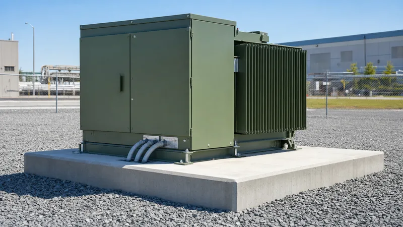
Quick answer: A transformer pad is an engineered reinforced concrete foundation that supports three-phase or single-phase pad-mounted transformers, maintains strict electrical clearances, and secures underground medium-voltage (MV) and low-voltage (LV) cable entries. It isolates live assets from moisture, resists ground subsidence, and provides a structural anchor designed to withstand operational vibration, seismic forces, and short-circuit mechanical stresses.
In commercial, utility, and renewable energy installations, improper foundation design represents one of the most frequent root causes of enclosure distortion, cable termination strain, and moisture ingress. Whether designing for standard commercial distribution or complex networks like radial feed vs loop feed layouts, selecting the correct foundation parameters ensures decades of trouble-free operation.
Functional Requirements of a Concrete Pad for Transformer Installations
A concrete pad for transformer installations must safely resist combined static and dynamic load vectors while maintaining rigid spatial geometry for conduits. Standard liquid-immersed pad-mounted transformers range in weight from 1,200 kg for 75 kVA units up to 12,000 kg or more for 3,000 kVA systems. The foundation must transfer this static load evenly to prevent differential settling, which risks misaligning internal busbars or placing destructive shear stresses on medium-voltage cable terminations.
Beyond gravity loads, the foundation must comply with dynamic operational demands. IEEE C57.12.28 defines structural enclosure integrity and anchoring requirements to protect against external mechanical tampering, wind load vectors, and short-circuit electromagnetic forces. Cable management is equally critical: the pad incorporates dedicated open block-outs or precisely cast PVC conduits that segregate MV primary cables (typically 11 kV to 34.5 kV) from LV secondary runs (typically 400 V to 480 V). Foundations must also incorporate dedicated grounding provisions, such as copper-clad ground rods driven through the pad aperture and bonded directly to the equipment earth busbar according to IEEE 80 standards.
Precast Transformer Pad vs Cast-in-Place Foundations
Specifying engineers must evaluate whether a precast transformer pad or a poured cast-in-place (CIP) slab best suits project timelines, logistics, and ground conditions. A precast concrete transformer pad is manufactured under strict factory quality controls with certified aggregate grading, precise water-to-cement ratios, and steam or controlled ambient curing. This eliminates the field risks of unverified concrete mix quality, inadequate rebar placement, or poor on-site hydration during freezing or rainy weather.
Conversely, cast-in-place concrete offers flexibility for sites with unconventional geometry, exceptionally high transformer mass (exceeding 15,000 kg), or complex internal cable duct banks requiring bespoke formwork. However, CIP construction introduces extensive project delays, requiring formwork carpentry, rebar tying, concrete testing, and a mandatory 7- to 28-day hydration period before electrical crews can stage the transformer.
| Evaluation Metric | Precast Transformer Pad | Cast-in-Place Concrete Pad |
|---|---|---|
| Installation Time | 1 to 3 hours (rig and set) | 7 to 28 days (pour, cure, strip) |
| Compressive Strength | Typically 35 to 45 MPa (factory-cured) | Typically 25 to 30 MPa (site-dependent) |
| Weather Sensitivity | Zero site-weather delays | Severe risk from rain, frost, or heat |
| Dimensional Accuracy | ±3 mm tolerance on conduit openings | ±12 mm tolerance (field formwork) |
| Labor Requirement | Small crane crew (2-3 persons) | Formwork, steel-fixing, concrete teams |
| Initial Procurement Cost | Moderate to high initial logistics cost | Lower material cost, higher site labor |
| Best Application | Standard commercial, renewable sites | Heavy bespoke substations, rocky slopes |
Structural Sizing Rules and Calculation Example
Structural sizing of a transformer pad requires verifying concrete thickness, edge distances, and sub-base bearing pressure against site soil capacities. Foundation sizing must accommodate the transformer tank footprint plus an extension of at least 150 mm on each side. The slab thickness typically ranges from 150 mm for light units to 300 mm for multi-megavolt-ampere equipment, reinforced with ASTM A615 Grade 60 (or BS 4449 Grade 500) high-yield steel mesh.
Consider a practical engineering calculation for a 1,500 kVA pad-mounted transformer:
- Transformer total wet mass ($M$): 5,200 kg (weight $W_t = 5,200 \times 9.81 = 51.01\text{ kN}$)
- Cabinet dimensions: 1,800 mm (width) $\times$ 1,600 mm (depth)
- Specified pad dimensions ($L \times B$): 2,200 mm $\times$ 2,000 mm (Area $A = 4.40\text{ m}^2$)
- Pad thickness ($t$): 0.20 m (reinforced concrete density $\rho_c = 2,400\text{ kg/m}^3$)
- Pad mass: $2.2 \times 2.0 \times 0.20 \times 2,400 = 2,112\text{ kg}$ ($W_p = 20.72\text{ kN}$)
- Total static weight ($W_{total}$): $51.01\text{ kN} + 20.72\text{ kN} = 71.73\text{ kN}$
Calculate the applied soil bearing pressure ($q$):
$$q = \frac{W_{total}}{A} = \frac{71.73\text{ kN}}{4.40\text{ m}^2} = 16.30\text{ kPa (kN/m}^2\text{)}$$
Typical medium-density compacted sub-bases demonstrate an allowable bearing capacity of 100 kPa to 150 kPa. The calculated 16.30 kPa represents a safety factor greater than 6.0 against shear failure, confirming the 200 mm thickness and footprint dimensions are structurally sound. For installations integrated with high-density infrastructure such as transformers for data centers, seismic hold-down anchor shear stresses must also be calculated per ASCE 7-16 Chapter 13.
Clearance Rules, Fire Safety, and Conduit Placement
Clearance around a transformer pad must strictly comply with national safety standards to ensure operator protection and mitigate structural fire exposure. NFPA 70 (NEC) Section 110.26 stipulates working clearances: maintaining at least 0.9 m to 1.2 m of clear distance in front of electrical compartments for equipment up to 1,000 V, increasing to 1.5 m or more for MV compartments. Furthermore, utility standards routinely require 2.4 m to 3.0 m of unobstructed access directly in front of cabinet doors to facilitate hot-stick switching.
Fire safety siting rules dictated by insurance directives and building regulations require specific spatial separations between oil-filled distribution transformers and building envelope features. For liquid-insulated transformers containing mineral oil, a minimum clearance of 3.0 m from combustible walls, windows, and fire escapes is standard; where non-combustible walls are present, clearances may reduce to 1.5 m. For deeper fire mitigation strategies, review our transformer fire protection system guide.
Conduit placement must match the equipment manufacturer termination window precisely. Medium-voltage primary conduits enter the pad through the designated high-voltage compartment block-out (typically on the left when facing the unit), whereas low-voltage cables terminate through the right-hand aperture. Conduits must terminate 50 mm to 75 mm above finished concrete pad level, fitted with grounding bushings to protect insulation from abrasion and prevent moisture pooling from running down the ductwork.
Step-by-Step Installation Procedure for a Precast Concrete Transformer Pad
Installing a precast concrete transformer pad requires careful ground preparation and rigging protocols to prevent future slab tilt and structural cracking.
- Excavation and sub-grade verification: Excavate the target footprint to a depth of 300 mm to 400 mm below grade, ensuring the base is level and free of organic matter. Proof-roll the subgrade to verify it meets local geotechnical bearing specifications.
- Sub-base gravel placement: Place a 150 mm thick bed of crushed, well-graded aggregate (such as ASTM D2940 dense-graded aggregate). Compact the aggregate mechanically in lifts to a minimum of 95% Modified Proctor density under ASTM D1557.
- Earth grounding infrastructure: Drive standard 16 mm diameter copper-clad steel ground rods through the subgrade inside the designated open compartment window, leaving adequate shank length to connect the substation grounding grid.
- Rigging and pad placement: Lift the precast unit using certified lifting clutches inserted into the integrated cast-in lifting anchors. Lower the slab smoothly onto the prepared sub-base, checking elevation with a laser level across all four corners to confirm deviation is under 3 mm.
- Conduit alignment: Thread primary and secondary conduits through the pad block-outs, applying non-shrink grouting or expanding mechanical boots around pipe entries to block vermin and sub-slab moisture ingress.
- Equipment landing and anchoring: Rig and position the pad-mounted transformer on the pad. Secure the cabinet perimeter using stainless steel hold-down cleats bolted into pre-cast cast-in threaded inserts, torquing to manufacturer specifications.
Procurement and Site Inspection Checklist
Engineers and procurement teams must inspect all foundation elements prior to placing transformers on site. Use this practical verification checklist before signing off on pad delivery or commissioning:
- Concrete Mix Verification: Batch plant test certificates confirming 28-day compressive strength $\ge 28\text{ MPa}$ ($\ge 4,000\text{ psi}$), with water-cement ratio $\le 0.45$.
- Curing Method: Factory documentation certifying compliant moist or membrane curing per ACI 308R.
- Dimensional Tolerances: Length, width, and depth within $\pm 6\text{ mm}$; diagonal squareness within $\pm 5\text{ mm}$.
- Block-out Location: Conduit window alignment matches the transformer HV/LV terminal layout drawings within $\pm 3\text{ mm}$.
- Surface Finish: Broom-finish or light float finish on walking surfaces; smooth, flat, unblemished mounting perimeter for tank gaskets.
- Chamfering: All exposed perimeter top edges cast with a minimum $20\text{ mm} \times 20\text{ mm}$ chamfer to resist chipping and corner spalling.
- Grounding Inserts: Embedded grounding nuts or pass-through windows clean, unthreaded, and deburred.
- Site Bearing Capacity: Dynamic cone penetrometer or plate load test confirming minimum subgrade bearing capacity of $100\text{ kPa}$.
For installations undergoing full substation commissioning, refer to our comprehensive substation testing guide for primary injection, insulation resistance, and grid earth bonding verification.
Next steps: specifying and sourcing
Specifying the optimal transformer pad requires aligning foundation mechanical load ratings, internal cable clearance windows, and environmental durability with your equipment configuration. Our engineering team designs and manufactures high-efficiency medium-voltage distribution equipment, including pad-mounted transformers, modular prefabricated substations, and custom oil-immersed transformers built to IEEE, ANSI, and IEC standards.
When preparing your tender documentation, submit your site geotechnical reports, single-line diagrams, and equipment weight schedules. Visit our transformer quotation page or contact our technical sales desk to discuss project-specific foundation footprint drawings and complete substation equipment packages.
Frequently asked questions
What is the standard thickness of a transformer pad?
The standard thickness of a concrete transformer pad ranges between 150 mm and 250 mm for typical distribution ratings up to 2,500 kVA. Larger power units or installations situated on poor soils may require thicknesses of 300 mm or more to prevent slab deflection and structural cracking.
Can you put a transformer directly on the ground?
No, a pad-mounted transformer cannot be set directly on the ground because soil subsidence, surface runoff, and moisture ingress will corrode the enclosure and damage underground cable terminations. A solid concrete foundation is legally required by electrical codes including NEC Section 110.26 and IEEE standards.
How far must a transformer pad be from a building?
A transformer pad for an oil-immersed unit must typically be placed at least 3.0 m from combustible walls, windows, and doors to satisfy fire protection standards. When adjacent to non-combustible masonry construction with zero openings, this separation distance can often be reduced to 1.5 m depending on local utility codes.
What concrete strength is required for a transformer pad?
A transformer pad requires concrete with a minimum 28-day compressive strength of 28 MPa (4,000 psi) under ASTM C39. Many precast specifications mandate 35 MPa (5,000 psi) or higher to withstand freeze-thaw cycles, chemical exposure, and heavy equipment handling.
Why are precast transformer pads preferred over cast-in-place pads?
Precast pads are preferred because they eliminate on-site concrete curing times, reducing field work from weeks to hours while ensuring strict factory-controlled compressive strength and dimensional precision. They allow immediate equipment landing and cable pull-in without schedule delays.
Tags: transformer pad precast transformer pad concrete pad for transformer precast concrete transformer pad


