Key takeaways
- Data center transformers operate under continuous high-load factors with severe non-linear harmonic distortion, requiring tailored core geometries and winding configurations.
- Dry-type cast resin units predominate in white space and indoor electrical rooms due to strict fire safety mandates under NFPA 75 and IEC 61936-1.
- A dedicated K-factor rating (typically K-9 to K-13) calculated per IEEE C57.110 is essential to prevent hot-spot overheating induced by server power supply switch-mode harmonics.
- Because data centers run continuously (8,760 hours per year), capitalised evaluation of no-load losses (core) often outweighs initial equipment capital expenditure within 3 to 5 years.
- Specified impedance (%Z) must balance downstream short-circuit fault current limits on low-voltage switchboards against system voltage drop and transient motor inrush during utility failover.
Quick answer: Transformers for data centers are mission-critical power distribution assets engineered to supply continuous, non-linear computing loads with maximum reliability, high efficiency, and low acoustic emissions. They require specialized harmonic mitigation (K-factor or harmonic mitigation windings), tight impedance tolerances to manage fault levels, and advanced thermal design to prevent insulation breakdown under 24/7 continuous operation.
Electrical infrastructure within modern mission-critical facilities must deliver continuous power availability while accommodating high power densities, severe harmonic currents, and stringent energy efficiency benchmarks. Enterprise and hyperscale facilities cannot tolerate unmanaged voltage sags, overheating, or nuisance tripping. Consequently, selecting the correct distribution and substation transformers forms the backbone of data hall availability.
Specifying transformers for data centers involves balancing environmental constraints, acoustic targets, fire codes, and electrical performance parameters. While conventional commercial distribution networks experience cyclic, predictable loading, a data center transformer routinely handles continuous baseload operation alongside elevated harmonic content generated by switch-mode power supplies (SMPS) and variable-frequency drives (VFDs) running chilled-water pumps. This engineering guide details the mechanical, magnetic, and thermal design parameters necessary to procure and deploy reliable transformers across hyperscale, colocation, and edge installations.
Key Requirements for Transformers for Data Centers
Continuous baseload duty, strict thermal headroom, and exceptional power quality resilience are the primary design drivers for mission-critical transformers. Unlike commercial office buildings where load curves drop significantly outside standard operational hours, a hyperscale compute hall maintains a continuous load factor often exceeding 75% to 85% around the clock.
To guarantee an operational lifespan of 30 years or more under these conditions, standard catalog distribution units are rarely adequate. Engineers must evaluate several mission-critical parameters:
- Continuous Thermal Endurance: Units must be rated for continuous full-load operation at maximum ambient design temperatures (typically 40°C ambient, 30°C daily average per IEC 60076-1 clause 5.1). Specifying a lower average winding temperature rise—such as an 80°C or 100°C rise on Class 220 (Class H) insulation materials—creates built-in thermal margins that extend insulation life and permit emergency overload without degrading the dielectric medium. See our Winding Temperature Guide for comprehensive degradation formulas.
- Energy Efficiency Mandates: Global energy regulations, including the European EcoDesign Directive (EN 50588-1 Tier 2) and the United States Department of Energy (DOE 2016 / 10 CFR Part 431), establish mandatory minimum efficiency standards. In continuous facilities, lower core losses (no-load losses) directly translate into reduced power usage effectiveness (PUE) overhead and lower cooling plant heat loads.
- Acoustic Noise Mitigation: Data hall power rooms and perimeter plant areas often sit adjacent to offices or property boundaries with strict decibel boundaries. Transformers must be specified with core noise levels 3 to 10 dB(A) below standard NEMA TR-1 or IEC 60076-10 thresholds by reducing core magnetic flux density (operating below 1.6 Tesla) and utilizing step-lap mitered joints on high-permeability grain-oriented silicon steel (CRGO).
- Redundancy Topologies: System designers use 2N (system plus system) or distributed redundant topologies. Transformers must seamlessly accept sudden 100% step-load transfers without dropping output voltage below the ITIC/CBEMA power tolerance curves when a parallel supply train trips.
Dry-Type vs Liquid-Filled Data Center Transformer Selection
Choosing between dry-type and liquid-filled construction depends primarily on substation location, spatial constraints, local building fire codes, and environmental safety regulations. Both technologies possess proven reliability profiles, yet their operational strengths align with different points in the campus electrical topology.
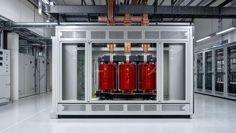
Indoor installations inside the main facility envelope—especially those positioned on intermediate equipment mezzanine floors or directly adjacent to white space—almost universally mandate dry-type units. Cast resin dry-type transformers encapsulate the medium-voltage (MV) and low-voltage (LV) windings in vacuum-cast epoxy, making them flame-retardant, self-extinguishing, and moisture-resistant. This completely eliminates the need for blast-rated bunker construction, oil containment curbs, or active deluge piping mandated by NFPA 75 and NFPA 855. For details on passive and active fire mitigation, refer to our guide on Transformer Fire Protection Systems.
Conversely, for outdoor yard substations or external pad-mounted enclosures stepping down utility grid voltages (such as 33 kV, 66 kV, or 110 kV down to internal distribution levels like 11 kV or 4.16 kV), liquid-immersed transformers offer clear technical advantages. Liquid units provide superior dielectric clearance, higher total kVA ratings within a smaller physical footprint, and an extended operational life under harsh external atmospheric conditions. Modern hyperscale facilities increasingly deploy natural synthetic ester fluids instead of mineral oil. Ester fluids feature a high fire point (>300°C, K-class per IEC 61039), offering high fire safety margins and biodegradable spill performance while reducing required separation distances under IEC 61936-1.
| Design Parameter | Cast Resin Dry-Type | Vacuum Pressure Impregnated (VPI) | Synthetic Ester Liquid-Filled | Mineral Oil Liquid-Filled |
|---|---|---|---|---|
| Installation Location | Indoor / Mezzanine / Close to IT | Indoor dry clean rooms | Outdoor / Close perimeter / Enclosed vault | Outdoor substation yard only |
| Dielectric / Cooling Medium | Solid Epoxy Resin (Air natural/forced) | Air / Varnish (Class H/C) | Synthetic Ester Fluid (KNAN/KNAF) | Mineral Oil (ONAN/ONAF) |
| Fire Safety Classification | F1 (Self-extinguishing, IEC 60076-11) | Non-propagating, low smoke | K-Class (Fire point ≥ 300°C) | O-Class (Fire point ~165°C) |
| Efficiency Profile | High efficiency at low-to-medium load | Moderate efficiency | High efficiency across wide load curve | Highest peak efficiency; lowest losses |
| Containment Requirement | None required | None required | Catch basin / Bund wall (reduced) | Full bund wall + oil-water separator |
| Acoustic Noise (NEMA TR-1 baseline) | Moderate (requires core de-fluxing) | Moderate to High | Low (fluid dampens core vibration) | Low (fluid dampens core vibration) |
| Maintenance Demand | Visual inspection, torque check, dusting | Periodic vacuuming, dry environment | Periodic fluid DGA, dielectric tests | Frequent fluid DGA, moisture monitoring |
Harmonic Mitigation and K-Factor Sizing per IEEE C57.110
Harmonic currents generated by IT server power supplies cause disproportionate core and winding heating that will destroy a standard distribution transformer if derating or specialized construction is omitted. Server racks utilize switched-mode power supplies that draw current in pulses rather than pure sinusoidal waveforms, injecting high proportions of 3rd, 5th, 7th, 9th, and 11th order harmonics into the electrical distribution system.
Harmonic currents increase transformer losses through two primary mechanisms: elevated winding eddy-current losses (which increase proportionally with the square of the harmonic frequency and current, $I_h^2 \times h^2$) and increased stray load losses in structural steel clamps and tanks. To prevent localized hot-spot breakdown of winding insulation, engineers specify transformers designed to withstand these thermal stresses, designated by a K-factor rating per IEEE C57.110 or an equivalent factor $K_f$ per BS EN 50541-1.
Standard linear transformers possess a rating of K-1. In modern data halls equipped with active power factor corrected (PFC) power supplies, current total harmonic distortion ($THD_i$) at full load typically ranges between 5% and 12%, yielding an operating requirement between K-4 and K-9. However, during partial load operation or when supplying mechanical infrastructure equipped with 6-pulse VFDs, harmonics rise sharply, requiring K-13 or even K-20 rated units.
Worked Engineering Calculation: Determining K-FactorTo establish the required K-factor for a 2,000 kVA, 11 kV to 415 V data hall distribution transformer, the design engineer must analyze the measured or projected harmonic spectrum of the connected load under worst-case operational conditions. The standard formula defined in IEEE C57.110 is:
$K = \sum_{h=1}^{h_{max}} \left( \frac{I_h}{I_1} \right)^2 \times h^2 \Big/ \sum_{h=1}^{h_{max}} \left( \frac{I_h}{I_1} \right)^2$
Consider a facility where non-linear server power supplies and plant drives produce the following harmonic profile relative to fundamental current ($I_1 = 1.00$ pu):
- Fundamental ($h=1$): $I_1 = 1.000$ pu → $I_1^2 \times 1^2 = 1.0000$
- 3rd Harmonic ($h=3$): $I_3 = 0.080$ pu → $I_3^2 \times 3^2 = 0.0064 \times 9 = 0.0576$
- 5th Harmonic ($h=5$): $I_5 = 0.220$ pu → $I_5^2 \times 5^2 = 0.0484 \times 25 = 1.2100$
- 7th Harmonic ($h=7$): $I_7 = 0.160$ pu → $I_7^2 \times 7^2 = 0.0256 \times 49 = 1.2544$
- 9th Harmonic ($h=9$): $I_9 = 0.040$ pu → $I_9^2 \times 9^2 = 0.0016 \times 81 = 0.1296$
- 11th Harmonic ($h=11$): $I_{11} = 0.110$ pu → $I_{11}^2 \times 11^2 = 0.0121 \times 121 = 1.4641$
- 13th Harmonic ($h=13$): $I_{13} = 0.080$ pu → $I_{13}^2 \times 13^2 = 0.0064 \times 169 = 1.0816$
Step-by-step summation:
- Calculate the sum of squares of the currents: $\sum (I_h/I_1)^2 = 1.000 + 0.0064 + 0.0484 + 0.0256 + 0.0016 + 0.0121 + 0.0064 = 1.1005$
- Calculate the weighted harmonic loss factor numerator: $\sum [ (I_h/I_1)^2 \times h^2 ] = 1.0000 + 0.0576 + 1.2100 + 1.2544 + 0.1296 + 1.4641 + 1.0816 = 5.1973$
- Divide the numerator by the denominator: $K = 5.1973 / 1.1005 = 4.722$
Conclusion: The baseline operating load requires a minimum K-factor of 4.72. To accommodate future server hardware refresh cycles with different harmonic profiles and avoid operating on the thermal limit, standard engineering practice dictates rounding up to the next industry standard tier: a K-9 or K-13 rated transformer must be specified. Manufacturers construct K-13 units using thinner, individually insulated transposed conductors or foil windings to minimise high-frequency skin and proximity effects, alongside enlarged neutral conductors rated for 200% of the phase current to handle uncancelled triplen harmonics.
Efficiency Standards, Total Cost of Ownership, and Loss Capitalisation
Evaluating transformers based strictly on initial purchase price is an expensive mistake in data center design. Because these assets operate continuously at high load factors, the cumulative cost of electricity consumed by transformer internal losses over a 20- to 30-year lifecycle frequently exceeds the original equipment purchase price by a factor of three to five.
Total transformer losses comprise two elements:
- No-Load Losses ($P_0$, Core Losses): Hysteresis and eddy current losses within the magnetic core. These remain energized and constant 8,760 hours a year, regardless of whether the IT servers are at idle or drawing full computing power.
- Load Losses ($P_k$, Copper/Conductor Losses): Resistance ($I^2R$) and stray losses that vary with the square of the operating load current.
Consulting engineers apply Total Cost of Ownership (TCO) loss capitalisation formulas inside tender documents to evaluate competing factory bids. The standard capitalisation equation is:
$TCO = C_{purchase} + (A \times P_0) + (B \times P_k)$
Where $C_{purchase}$ is the procurement cost, $P_0$ is guaranteed no-load loss (kW), $P_k$ is guaranteed load loss at rated base kVA (kW), and $A$ and $B$ represent the capitalized economic value of losses ($/kW) over the operational horizon:
$A = \frac{(1 + i)^n - 1}{i \times (1 + i)^n} \times 8760 \times C_{energy} \times \left(1 + \frac{1}{COP}\right)$
$B = \frac{(1 + i)^n - 1}{i \times (1 + i)^n} \times 8760 \times C_{energy} \times \left( \frac{S_{actual}}{S_{rated}} \right)^2 \times \left(1 + \frac{1}{COP}\right)$
Where $i$ is the project discount rate, $n$ is system lifespan (e.g. 20 years), $C_{energy}$ is the cost per kWh of electricity, $S_{actual}/S_{rated}$ is the average loading factor, and $COP$ is the coefficient of performance of the facility cooling plant. Because every watt of heat dissipated by an indoor transformer must be removed by the facility HVAC or chilled-water plant, the cooling penalty factor $[1 + (1/COP)]$ significantly increases the financial value of $A$ and $B$.
A bid offering a lower initial purchase price but featuring standard silicon steel will incur massive lifecycle costs compared to a higher-specification transformer built with laser-scribed amorphous metal cores or high-grade domain-refined CRGO steel. Specifying amorphous cores can reduce no-load losses by up to 60% to 70% compared to standard core steel, offering exceptional return on investment in redundant 2N architectures where each transformer operates at an average load factor of only 35% to 45% under normal conditions.
Impedance, Short-Circuit Fault Levels, and Inrush Considerations
Selecting percentage impedance (%Z) requires balancing fault level suppression against system voltage stability. If %Z is too low, prospective short-circuit currents on downstream low-voltage switchgear exceed standard breaking capacities, requiring expensive high-AIC (ampere interrupting capacity) circuit breakers. Conversely, if %Z is too high, unacceptably large voltage drops occur during step-load changes, and severe transient voltage dips are triggered during transformer energisation.
For standard MV/LV unit substations stepping down 11 kV or 22 kV to 400 V or 480 V, target impedance values generally range between 6.0% and 8.0%. Consider the trade-offs governed by IEC 60076-5 and IEEE C57.12.00 Table 5:
- Fault Level Suppression: The maximum symmetrical short-circuit current ($I_{sc}$) at the secondary terminals is governed by $I_{sc} = I_{rated} / Z_{pu}$. For a 2,500 kVA, 415 V transformer ($I_{rated} \approx 3,478\text{ A}$), an impedance of 6.0% yields an available fault current of roughly 58 kA, which falls comfortably within standard 65 kA switchboard busbar and circuit breaker ratings. Specifying 5.0% impedance would push short-circuit currents to approximately 70 kA, forcing an expensive upgrade to 85 kA or 100 kA rated switchgear per IEC 61439 Low-Voltage Switchgear standards.
- Voltage Regulation: Under steady-state conditions, higher impedance increases internal voltage drop under low-power-factor scenarios. When large chiller motors or pumps start directly across the line, excessive transformer impedance can cause the LV bus voltage to drop below 90% of nominal, potentially initiating power supply drop-out on sensitive dual-corded IT equipment.
- Sympathetic Inrush and Paralleling: When a transformer is energized following an upstream automatic transfer switch (ATS) operation, magnetizing inrush current can peak at 8 to 12 times rated full-load current ($I_{flc}$) for several cycles. If an adjacent parallel transformer is already energised on the same medium-voltage busbar, the sudden flux change can induce "sympathetic inrush" in the operating transformer, leading to false differential relay trips. Protection engineers must specify core geometry and winding resistance capable of dampening inrush waveforms and ensure relays utilize 2nd harmonic restraint per our Transformer Protection Guide.
Acoustic Noise Control and Mechanical Resonance Prevention
Acoustic emissions from transformers represent a severe structural and regulatory challenge in hyperscale and urban multi-story facilities. The predominant source of noise is core magnetostriction—the physical expansion and contraction of silicon steel laminations under alternating magnetic flux—which occurs at twice the line frequency (100 Hz in 50 Hz systems, 120 Hz in 60 Hz systems) along with its higher harmonics.
In cast resin dry-type transformers, this mechanical vibration transmits directly through the frame, casing, and foundation mounts into structural concrete floor slabs, causing acoustic reverberation throughout white space halls and office suites. To eliminate structural and airborne transmission, engineering specifications must enforce strict acoustic controls:
- Flux Density De-rating: Standard commercial distribution transformers operate at magnetic flux densities between 1.65 and 1.75 Tesla. For mission-critical quiet designs, specifying an operational flux density limited to 1.45 to 1.55 Tesla reduces core noise generation by 5 to 10 dB(A) at the source.
- Step-Lap Core Joints: Core manufacturing must incorporate fully automated multi-step lap mitered 45° joints. This minimizes magnetic reluctance and air-gap turbulence at the corner joints of the limbs and yokes, substantially reducing the high-frequency acoustic hum.
- Anti-Vibration Isolation: Transformers must not be bolted rigidly to structural floors. Specifications should dictate factory-supplied double-deflection neoprene or spring-type anti-vibration mounts (AVMs) rated for minimum 95% isolation efficiency at 100/120 Hz. Flexible braided copper busbar connections must be installed between the transformer terminals and rigid busway or switchgear enclosures to prevent acoustic transmission through the power conductors.
Cooling Topologies and Dynamic Overload Sizing
Cooling architecture determines how effectively a transformer handles emergency overloads when a redundant power train fails. Transformers operate primarily with natural convective cooling, but modern facilities incorporate automated forced-air (AF) blower systems to provide dynamic peaking capacity without increasing physical footprint.
In standard 2N or N+1 architectures, each transformer operates normally at 40% to 50% capacity. If Transformer Train A trips, Transformer Train B must instantaneously absorb the entire load, transitioning from 50% to 100% (or more) rated capacity. Under an unexpected compute workload spike, this load can climb to 115% or 125% of baseline base rating.
For dry-type transformers, ratings are typically designated as AN/AF (Air Natural / Air Forced):
- Air Natural (AN) Rating: The continuous baseline rating without forced cooling fans. The transformer operates quietly, with minimal parasitic auxiliary power consumption and low thermal stress on the solid insulation.
- Air Forced (AF) Rating: Utilizing automatically controlled cross-flow tangential cooling blowers directed across the winding ventilation ducts increases the thermal dissipation capacity, providing an additional 25% to 40% kVA capacity (e.g., a 2,000 kVA AN rated transformer achieves 2,666 kVA under AF conditions).
When engineering these systems, forced-air blowers must be powered from uninterruptible power supply (UPS) backed auxiliary panels, monitored continuously through digital temperature controllers via embedded PT100 RTD sensors buried in the center of each phase winding. Cooling redundancy must be factored: if one blower fan fails, the control system must alarm and adjust thermal capacity calculations accordingly.
For outdoor oil- or ester-filled units, modern installations utilize ONAF (Oil Natural Air Forced) cooling with multi-stage variable speed fans to smoothly ramp thermal exchange while maintaining low acoustic noise during partial-load conditions.
Factory Acceptance Testing and RFQ Specification Checklist
Rigorous quality control and comprehensive Factory Acceptance Testing (FAT) guarantee that transformers perform to specification before arriving at the job site. Once cast in solid epoxy or sealed with synthetic ester, rectifying internal design errors or assembly flaws is prohibitively expensive and leads to massive schedule delays.
Every project specification should demand complete routine and type test documentation executed in compliance with IEC 60076 or IEEE C57.12.90. For an in-depth breakdown of standard testing procedures, refer to our comprehensive guide on Power Transformer Testing. The specification checklist below outlines the core mechanical, electrical, and thermal parameters an engineer should paste into an RFQ package:
| Specification Field | Required Value / Engineering Standard | Factory Compliance Verification Method |
|---|---|---|
| Applicable Standards | IEC 60076 (Parts 1-11) or IEEE C57.12.00 / C57.12.90 | Factory Quality Accreditation (ISO 9001/14001) |
| Transformer Type | Cast Resin Dry-Type or Synthetic Ester Liquid-Filled | Material safety data sheets & construction drawings |
| Rated Power (kVA/MVA) | Base AN / KNAN rating with +33% AF / KNAF capability | Temperature rise type test report |
| Voltage Ratio & Vector Group | e.g., 11,000 V to 415/240 V, Dyn11 (or Dyn1) | Turns ratio and vector group verification test |
| Winding Material | Electrolytic Copper (Class 1, purity ≥ 99.9%) | Material mill certificates & resistance measurement |
| Harmonic K-Factor Rating | K-9, K-13, or K-20 rated per IEEE C57.110 | Stray and eddy loss calculation data sheet |
| Short-Circuit Impedance (%Z) | 6.0% to 8.0% (±5% factory tolerance per IEC) | Impedance voltage and load loss test |
| Maximum Sound Pressure Level | 3 to 8 dB(A) below standard NEMA TR-1 thresholds | Sound level test per IEC 60076-10 |
| Partial Discharge Level | ≤ 10 pC at 1.3 times rated line-to-neutral voltage | Partial discharge routine test (mandatory for cast resin) |
| Loss Guarantees | Strict maximum $P_0$ (kW) and $P_k$ (kW) per EcoDesign/DOE | Calibrated power analyzer loss measurement at FAT |
| Thermal Monitoring | Dual PT100 RTDs per phase (alarm & trip) + 4-20mA/RS485 | Sensor calibration and trip simulation test |
| Enclosure Protection Rating | IP21 or IP31 (Indoor Dry); IP55 / NEMA 3R/4 (Outdoor) | Ingress protection type certification |
Next steps: specifying and sourcing
Selecting and procuring the right power equipment requires translating complex data hall load profiles into precise technical specifications. When submitting a request for quotation, ensure your tender package contains complete single-line diagrams, short-circuit requirements, harmonic distortion spectrums, and loss capitalisation figures ($A$ and $B$ factors).
Explore our industrial range of high-efficiency dry-type transformers engineered for indoor data hall substations, or evaluate our heavy-duty oil-immersed transformers and power transformers for utility-scale campus step-down applications. For integrated exterior plant space, consider our pre-engineered compact transformer substations. Contact our application engineering team directly via our quote request portal to review your single-line diagrams and receive customized factory loss and acoustic data.
Frequently asked questions
Why are dry-type transformers preferred for indoor data center installations?
Dry-type cast resin transformers do not contain flammable liquid, making them compliant with indoor fire regulations under NFPA 75 and IEC 61936-1. They eliminate the need for blast vaults, fire-suppression deluge systems, and oil containment basins, allowing them to be installed directly on equipment floors close to IT server racks.
What K-factor rating is typically required for transformers for data centers?
Most modern facilities require transformers rated between K-9 and K-13 per IEEE C57.110. Although active power factor correction on newer servers keeps total harmonic distortion relatively low during balanced operations, partial loads, redundant configurations, and motor drives generate substantial harmonic currents that require specialized winding transposition.
How does transformer efficiency impact data center Power Usage Effectiveness (PUE)?
Because transformers operate continuously 8,760 hours per year, all internal core and winding losses convert directly into heat. This heat must be removed by the facility cooling infrastructure, meaning one kilowatt of transformer loss actually consumes 1.2 to 1.4 kilowatts of total facility power depending on cooling efficiency, directly inflating the facility PUE.
What is the typical impedance value for a data center transformer?
Impedance (%Z) for data hall medium-to-low voltage distribution transformers is typically specified between 6.0% and 8.0%. This range provides sufficient short-circuit fault current limitation to allow the use of standard commercial low-voltage switchboards (such as 65 kA breakers) while preventing excessive steady-state voltage drop and severe inrush dips.
Can synthetic ester fluids replace mineral oil in data center transformers?
Yes, synthetic ester fluids are widely used in modern mission-critical facilities because they possess a fire point exceeding 300°C (K-class). This significantly reduces fire clearance requirements under building insurance guidelines while offering non-toxic, fully biodegradable protection against environmental spills in outdoor substations.
What is the role of electrostatic shielding in data center transformers?
An electrostatic shield is a grounded copper screen placed between the primary and secondary windings. It prevents high-frequency common-mode electrical noise, utility switching surges, and transient spikes on the medium-voltage grid from capacitively coupling into the low-voltage windings supplying sensitive IT power distribution units.
Tags: transformers for data centers data center transformer dry-type transformer K-factor harmonics substation design


