Key takeaways
- A 480 277 transformer provides 480 V phase-to-phase for three-phase motor loads and 277 V phase-to-neutral for commercial lighting circuits.
- The secondary full-load current of a 500 kVA, 480Y/277 V transformer is 601.4 A, producing approximately 10.46 kA of symmetrical fault current at 5.75% impedance.
- Separately derived 480Y/277 V systems require neutral bonding to the grounding electrode conductor in compliance with NEC Article 250.30.
- A 480v step down transformer often steps 480 V delta down to 208Y/120 V to feed standard convenience receptacles and sensitive IT loads.
- Factory acceptance testing for these units requires insulation resistance, winding resistance, turns ratio, and short-circuit impedance verification per IEEE C57.12.90.
Quick answer: A 480 277 transformer is a three-phase electrical distribution transformer with a secondary winding arranged in a four-wire wye configuration delivering 480 V line-to-line and 277 V line-to-neutral. It serves as the primary backbone for North American commercial and industrial facilities, supplying large motor and mechanical plant at 480 V while directly feeding commercial luminaire circuits at 277 V.
In modern industrial facilities, hospitals, and commercial buildings, matching utilisation voltage to load demands is essential for electrical efficiency. Distribution topologies frequently rely on either stepping medium-voltage utility feeds (such as 13.8 kV or 4.16 kV) down to 480Y/277 V, or using a 480 step down transformer to supply lower-voltage utilisation equipment. Understanding winding configurations, thermal performance, and short-circuit dynamics ensures correct specification without premature insulation failure or nuisance breaker tripping. Engineers specifying equipment through our pad-mounted transformer and distribution ranges must balance transformation ratios, impedance, and fault current handling.
Understanding the 480 277 transformer configuration
A 480 277 transformer features a secondary wye (star) winding where the line-to-line voltage is 480 V and the line-to-neutral voltage equals 480 divided by the square root of three, yielding 277.13 V. This relationship allows plant designers to draw high-power three-phase circuits for chillers, pumps, air handlers, and process machinery while simultaneously operating 277 V single-phase loads between any line conductor and the common neutral.
Most commercial buildings run fluorescent and LED lighting ballasts at 277 V to lower the operating current, allowing smaller cable cross-sections and longer circuit runs without excessive voltage drop. When stepping down from medium-voltage networks, the primary winding is typically connected in delta (Delta-Wye, or Dyn1 / Dyn11 under IEC conventions). The delta primary traps third-harmonic currents, preventing them from circulating into the upstream network, while establishing a clean, stable neutral point on the 480Y/277 V secondary. For large industrial sites, these transformers are commonly deployed within unit substation installations integrated directly with low-voltage switchgear.
480v step down transformer topologies: Delta vs Wye
Selection between delta and wye winding configurations depends directly on whether the unit functions as a service entrance transformer or an internal distribution unit. When specifying a 480v step down transformer within an internal power network, two distinct transformation schemes dominate industrial design:
- Medium-Voltage to 480Y/277 V: Utilises a delta primary (e.g., 13.8 kV or 4.16 kV delta) and a wye secondary. This configuration creates a separately derived system where the secondary neutral is grounded, supplying both 480 V three-phase equipment and 277 V single-phase lighting infrastructure.
- 480 V Delta to 208Y/120 V: Operates downstream from the main 480 V switchboard. The 480 V delta primary feeds a 208Y/120 V secondary to supply standard office branch circuits, sensitive electronics, and server racks. This topology isolates common-mode electrical noise between plant floors and office levels, aligning with design practices found in transformers for data centres.
- 480 V to 480Y/277 V Isolation: A 1:1 ratio delta-wye isolation transformer used where an ungrounded 480 V delta system must establish a reliable, grounded neutral to feed modern lighting and variable-frequency drive (VFD) loads without floating-neutral overvoltage hazards.
Specifying an incorrect vector group can introduce unintended phase shifts. Standard ANSI transformers feature a 30-degree secondary lag (Dyn1), whereas certain international designs adhere to alternative clock-hour notations per IEC 60076-1 clause 6. Paralleling units requires identical phase displacement, tap ratios, and percentage impedance to prevent destructive circulating currents.
Sizing calculation: kVA, full-load current and fault level
Accurate sizing of a 480 volt transformer prevents thermal overload while limiting available short-circuit currents to values manageable by downstream switchgear. The rated three-phase current is calculated using standard apparent power formulas:
Consider an industrial facility specifying a 500 kVA dry-type transformer with a primary rating of 13,800 V Delta and a secondary rating of 480Y/277 V, featuring an impedance of 5.75% (%Z = 0.0575):
- Calculate Secondary Full-Load Amperes (FLA):
Isecondary = S / (√3 × VLL)
Isecondary = 500,000 VA / (1.73205 × 480 V) = 500,000 / 831.38 = 601.4 A - Calculate Secondary Line-to-Neutral Voltage:
VLN = 480 V / 1.73205 = 277.13 V - Calculate Primary Full-Load Amperes:
Iprimary = 500,000 VA / (1.73205 × 13,800 V) = 500,000 / 23,898.3 = 20.92 A - Calculate Secondary Prospective Symmetrical Short-Circuit Current (assuming infinite bus):
Isc = Isecondary / (%Z / 100)
Isc = 601.4 A / 0.0575 = 10,459 A (10.46 kA)
This prospective fault current dictates the minimum interrupting rating for downstream switchboards. If the facility installs low-voltage distribution gear, assemblies must comply with busbar withstand ratings defined under IEC 61439 standards or UL 891 to prevent bus distortion during close-in short circuits.
Specification comparison for 480V distribution transformers
Engineers can evaluate transformer construction options across oil-immersed and ventilated dry-type technologies depending on installation environment, efficiency benchmarks, and maintenance profiles.
| Parameter | Ventilated Dry-Type | Liquid-Immersed (Mineral Oil) | Liquid-Immersed (Ester Fluid) |
|---|---|---|---|
| Applicable Standards | IEEE C57.12.01 / UL 1561 | IEEE C57.12.00 / IEC 60076 | IEEE C57.12.00 / IEC 60076-14 |
| Typical kVA Range | 15 kVA – 3,000 kVA | 75 kVA – 10,000 kVA | 75 kVA – 10,000 kVA |
| Insulation Class | 220 °C (Class H) | 105 °C (Class A) | 120 °C – 140 °C (Class E/B) |
| Temperature Rise | 80 °C / 115 °C / 150 °C | 65 °C | 65 °C / 75 °C |
| Fire Point | Non-combustible | 165 °C (Class O1) | >300 °C (less-flammable fluid) |
| Installation Location | Indoor electrical rooms | Outdoor substations / vaults | Indoor / near buildings |
| Cooling Mechanism | ANN / ANF (Air Natural/Forced) | ONAN / ONAF | KNAN / KNAF |
| BIL Rating (Secondary 480 V) | 10 kV – 30 kV | 30 kV | 30 kV |
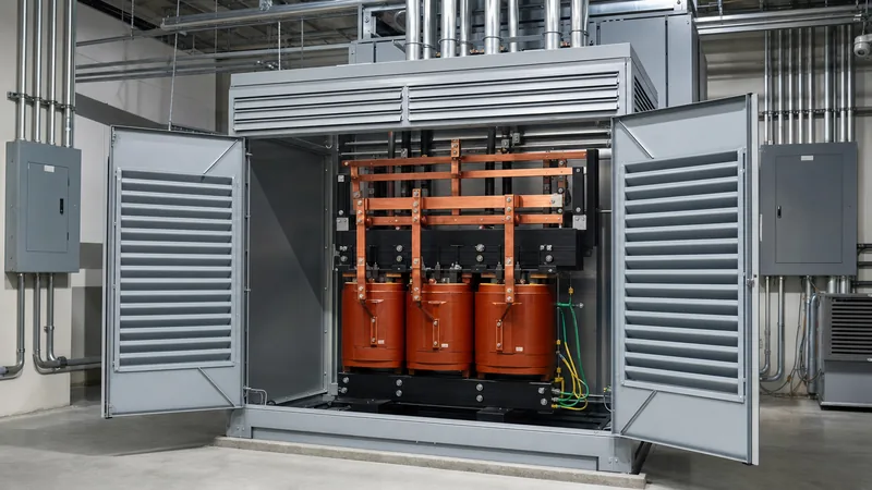
For indoor retrofits where liquid containment is impractical, our engineering team supplies dry-type transformers engineered with cast-resin or vacuum-pressure impregnated (VPI) windings, eliminating spill hazards and reducing fire-suppression capital costs.
Grounding and bonding requirements for 480Y/277 V systems
A 480Y/277 V transformer secondary constitutes a separately derived system under National Electrical Code (NEC / NFPA 70) Article 100. Correct grounding and bonding are mandatory to clear phase-to-ground faults rapidly and eliminate dangerous transient overvoltages.
In accordance with NEC Article 250.30, the secondary neutral must connect to a system bonding jumper that links the neutral terminal directly to the equipment grounding conductor enclosure. This connection must occur at a single point: either inside the transformer enclosure or within the first downstream disconnecting means (such as the main switchboard). Grounding electrode conductors must bond the neutral point to the building grounding grid or structural steel. Failing to install the bonding jumper leaves the neutral floating, exposing connected 277 V ballasts and power supplies to line-to-line overvoltages up to 480 V during accidental phase-to-ground faults.
Factory testing and commissioning inspection procedure
Verification of internal insulation integrity and correct turns ratio prevents in-service flashovers during commissioning. Factory and site acceptance testing must adhere strictly to IEEE C57.12.90 and NETA ATS standards using structured procedures.
- Visual and Mechanical Check: Verify nameplate ratings, phase markings (H1, H2, H3 and X0, X1, X2, X3), tap-changer position, enclosure earthing continuity, and internal clearances.
- Insulation Resistance Testing: Apply a calibrated megohmmeter at 1,000 V or 2,500 V DC between primary-to-secondary, primary-to-ground, and secondary-to-ground for 60 seconds. Minimum readings must exceed 1,000 megohms for modern dry-type systems at 20 °C.
- Voltage Ratio and Polarity Verification: Measure the turns ratio on all tap positions using a Three-Phase Transformer Turns Ratio (TTR) meter. Values must align with calculated nameplate ratios within ±0.5% tolerance as specified in IEEE C57.12.00 clause 9.1.
- Winding Resistance Measurement: Use a low-resistance Kelvin bridge to verify DC resistance across each winding phase, confirming balanced internal terminations and absence of loose bolted lugs. Detailed methodologies can be reviewed in our guide on how to test a transformer.
- Secondary Voltage Check at Energisation: Before applying plant load, energise the primary and verify phase-to-phase voltages (480 V ±2%) across each pair of secondary phase terminals, as well as phase-to-neutral voltages (277 V ±2%) from X0 to each respective line terminal.
Next steps: specifying and sourcing
When preparing an RFQ for a 480 277 transformer or an internal distribution 480v step down transformer, ensure your specification schedule includes primary and secondary nominal voltages, frequency (50 Hz or 60 Hz), vector group, basic impulse level (BIL), winding conductor material (copper or aluminium), and efficiency standards (such as DOE 2016 or IEC Ecodesign Tier 2). Review our heavy-duty oil-immersed transformers or ventilated dry-type units to select the appropriate build for your environment. Contact our electrical design specialists or submit your single-line diagrams via our transformer quotation request page for custom impedance profiling, loss evaluations, and certified factory drawings.
Frequently asked questions
What is the difference between 480V and 277V?
The difference is the measurement reference point within a wye-connected system. In a 480Y/277 V system, 480 V is the three-phase line-to-line voltage measured between any two phase conductors, while 277 V is the single-phase line-to-neutral voltage measured between any single phase conductor and the grounded neutral.
Can a 480 277 transformer run single-phase loads?
Yes, it can run single-phase loads connected either line-to-neutral at 277 V or line-to-line at 480 V. Single-phase 277 V branch circuits are standard for commercial lighting systems, but loads must be balanced evenly across all three phases to prevent neutral overheating and voltage unbalance.
Why is 277V commonly used for commercial lighting?
Utilising 277 V allows lighting circuits to draw roughly half the current of equivalent 120 V circuits for the same power output. This reduced current reduces branch-circuit I2R copper losses, allows longer circuit runs without excessive voltage drop, and decreases conduit and cable sizes across large facilities.
What size breaker is needed for a 480V step down transformer?
Breaker sizing depends on transformer kVA, impedance, and primary full-load current per NEC Article 450.3. Primary circuit breakers with no secondary protection typically require sizing up to 250% of the transformer primary full-load amperes, or 125% when coordinated with secondary overcurrent protection devices.
Can you backfeed a 480 step down transformer?
Backfeeding is technically possible but requires careful engineering review of the winding connections and core excitation. Reverse energisation introduces high initial inrush currents that can trip standard breakers, and standard delta-wye transformers cannot be reverse-fed to supply a grounded 480Y/277 V output without creating a floating, ungrounded delta connection.
Tags: 480 277 transformer 480v step down transformer 480 volt transformer 480 step down transformer


