Key takeaways
- A 480V transformer commonly steps distribution power down from 480V delta to 208Y/120V or 230V delta/wye for plant machinery and commercial sub-panels.
- Full-load primary current at 480V 3-phase is calculated as kVA / (0.48 × 1.732), yielding approximately 1.203 amperes per kVA.
- NEC Article 450 Table 450.3(B) mandates primary-only overcurrent protection at a maximum of 125% of rated current, or up to 250% when secondary protection is maintained at 125%.
- Impedance percentage directly dictates short-circuit fault levels, with a standard 112.5 kVA unit at 4.5% impedance delivering 3,007 amperes of symmetrical fault current on the 480V primary.
- Factory testing protocols must verify winding resistance, turns ratio, no-load losses, and insulation resistance in full compliance with IEEE C57.12.91 or IEC 60076-1.
Quick answer: A 480V transformer is an electrical distribution device engineered to step voltages down from, or step voltages up to, a 480-volt alternating current system, most frequently converting 480V 3-phase power to utilisation voltages such as 208Y/120V, 230V, or 400V.
In commercial and industrial distribution networks, 480V is the standard three-phase working voltage across North America and standard export process lines. Large motor control centres, industrial chillers, and heavy processing machinery operate natively on 480V feeds to minimise current draw and conductor cross-sections. However, auxiliary loads, imported production equipment, lighting networks, and control panels require lower potentials. Sizing and integrating a 480v transformer demands a precise balance between core-loss efficiency, fault-current withstand ratings, inrush handling, and thermal rise constraints. Whether specifying dry-type magnetic units for indoor mechanical rooms or liquid-immersed units for outdoor service, engineers must adhere strictly to design principles established in standards such as IEEE C57.12.00, NFPA 70 (NEC), and IEC 60076.
Core Operating Principles and Common 480V Configurations
A 480 volt transformer changes voltage levels via electromagnetic induction while isolating circuits or matching divergent distribution topologies. In commercial plants, the utility service often delivers 480V via a 3-phase, 3-wire delta or a 480Y/277V 4-wire wye topology. Facility engineers routinely install a 3 phase transformer 480v unit to feed subsystems requiring alternative voltages, utilizing distinct winding vectors to achieve phase displacement and neutral derivation.
The most common configurations include:
- 480V Delta to 208Y/120V Wye: The dominant commercial configuration in North America. The secondary neutral provides 120V line-to-neutral for convenience receptacles and office circuits, alongside 208V line-to-line for intermediate electrical apparatus. For non-linear electronic profiles, review the K Factor Transformer Guide to prevent harmonic overheating.
- 480V to 240V / 120V High-Leg Delta: Applied in legacy facilities requiring 240V three-phase for machinery alongside 120V single-phase power from a centre-tapped secondary winding leg.
- 480V to 230V 3 Phase: Widely specified for imported European or East Asian manufacturing equipment designed for 220V–240V nominal systems. When addressing smaller voltage variations within this band, refer to the Buck and Boost Transformer 208 to 240 Guide.
- 480V Delta to 400Y/230V Wye: Essential for running standard international (IEC) machinery within a domestic 480V utility environment, establishing a stable neutral point for single-phase 230V line-to-neutral loads.
For detailed comparisons on selecting low-voltage isolation gear versus other topologies, our Low Voltage Transformer Selection Guide covers core saturation limits and phase-matching considerations.
Step-Down Transformations: Sizing a 480V to 230V 3 Phase Transformer
Selecting a 480 step down transformer requires computing real power, reactive demand, continuous load margins, and starting inrush rather than simply matching nameplate kilowatts. Operating a 480v to 230v transformer with insufficient thermal or magnetic capacity results in nuisance tripping under motor-starting transients and accelerated insulation thermal degradation governed by the Arrhenius reaction rate.
To calculate the required three-phase capacity, use the standard power relationship:
$$\text{kVA} = \frac{V_{L-L} \times I_L \times \sqrt{3}}{1000}$$
Consider an industrial workshop adding an imported CNC milling machine that requires a 480v to 230v 3 phase transformer. The engineering load assessment shows:
- Connected motor and drive continuous load: 68 kW at a lagging power factor (PF) of 0.82.
- Apparent power requirement: 68 kW / 0.82 = 82.93 kVA.
- National Electrical Code continuous load safety factor (125% per NEC 215.2): 82.93 kVA × 1.25 = 103.66 kVA.
- Standard commercial size selection: Round up to the nearest standard rating, which is 112.5 kVA.
Now compute the operational full-load currents (FLA):
- Primary Full-Load Current (480V): $$I_{pri} = \frac{112,500\text{ VA}}{480\text{ V} \times 1.732} = 135.32\text{ A}$$
- Secondary Full-Load Current (230V): $$I_{sec} = \frac{112,500\text{ VA}}{230\text{ V} \times 1.732} = 282.41\text{ A}$$
If the secondary network experiences a bolted short-circuit fault, the transformer's internal per-unit impedance determines the maximum let-through energy. Assuming a standard nameplate impedance ($%Z$) of 4.5%:
$$I_{sc\text{ (primary)}} = \frac{I_{pri}}{\%Z / 100} = \frac{135.32\text{ A}}{0.045} = 3,007.1\text{ A}$$
This fault current level is vital for performing protective device coordination studies and verifying the interrupting capacity of upstream switchboards. For further guidance on voltage transformation between North American and international baselines, consult our 480V to 240V Transformer Guide.
Dry-Type vs Liquid-Immersed 480 Volt Transformer Design
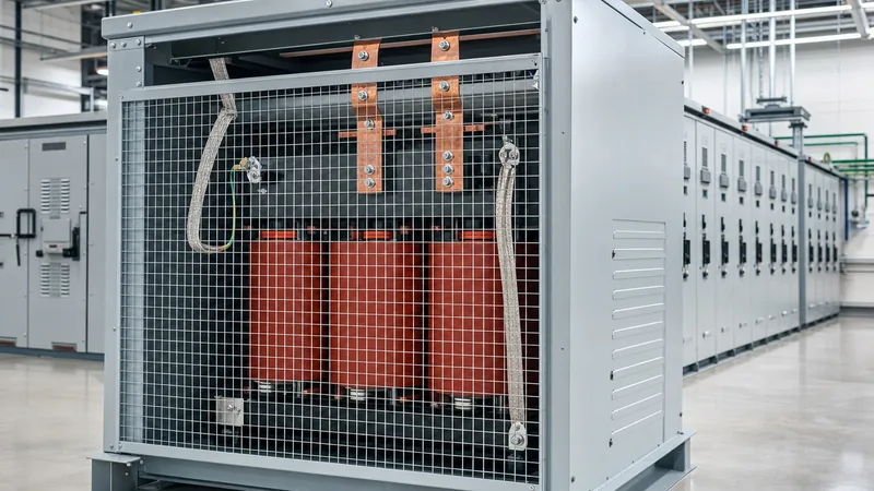
A 480 volt transformer is packaged either as an open/enclosed dry-type unit or as a liquid-immersed unit, depending on installation geography, environmental exposure, and spatial fire classifications. Dry-type designs dominate commercial indoor electrical rooms, whereas liquid-immersed units are preferred for outdoor substations, heavy industrial facilities, and pad-mounted applications.
| Engineering Metric | VPI Dry-Type Transformer | Cast Resin Dry-Type | Liquid-Immersed (Mineral Oil / Ester) |
|---|---|---|---|
| Applicable Standards | IEEE C57.12.01, UL 1561 | IEC 60076-11 | IEEE C57.12.00, IEC 60076-2 |
| Insulation Temperature Class | Class 220°C (H) | Class 155°C (F) or 180°C (H) | Class 105°C (A) / 120°C (Thermally upgraded) |
| Standard Temperature Rise | 150°C (optional 115°C or 80°C) | 100°C or 120°C | 65°C average winding rise |
| Basic Impulse Level (BIL) | 10 kV to 30 kV | 20 kV to 60 kV | 60 kV to 95 kV+ |
| Environmental Protection | NEMA 1 / 3R ventilated | IP54 / IP65 sealed enclosure | Hermetically sealed steel tank |
| Overload Capacity (Short-term) | Moderate (low thermal mass) | Moderate to high | Substantial (large liquid thermal reservoir) |
| Fire Risk Assessment | Low (self-extinguishing resin) | Minimal (non-flammable) | Requires containment and clearance buffers |
| Common Voltage Range | Up to 15 kV primary / 480V secondary | Up to 36 kV primary / 480V secondary | Up to 110 kV primary / 480V secondary |
Dry-type units operating at 480V typically utilise vacuum pressure impregnation (VPI) with high-grade polyester or silicone varnishes to resist airborne moisture and industrial particulates. Specifying an 80°C or 115°C temperature rise on a Class 220°C insulation system allows substantial continuous reserve capacity, yields lower operating core-and-coil losses, and extends operational longevity.
Overcurrent Protection and Grounding Under NEC Article 450
Overcurrent protection for every 480v transformer must comply strictly with NEC Article 450.3 to prevent thermal destruction from overloads and fire hazards under high-impedance faults. In addition, the creation of a Separately Derived System requires grounding electrode conductors sized in accordance with NEC Article 250.30.
Engineers generally employ one of two protection methodologies outlined in NEC Table 450.3(B) for transformers operating below 1000V:
- Primary-Only Protection: Permissible only when the secondary conductor run is brief and satisfies feeder tap rules. If the primary full-load current is 9 amperes or greater, the primary overcurrent protective device (OCPD) must not exceed 125% of rated current. If 125% does not correspond to a standard fuse or circuit breaker rating, NEC 450.3(B) allows rounding up to the next standard protective device size.
- Primary and Secondary Protection: Where primary overcurrent protection is set up to 250% to prevent nuisance tripping caused by high magnetic inrush currents (typically 8 to 12 times FLA for dry-type designs), secondary overcurrent protection must be installed and set at no more than 125% of the secondary FLA.
Grounding is critical when configuring a wye-connected secondary (such as stepping down from 480V Delta to 208Y/120V or 400Y/230V). The secondary neutral point must bond directly to the grounding electrode system via a properly sized grounding electrode conductor (GEC). A main bonding jumper must be installed between the neutral busbar and the transformer enclosure ground bus inside the unit or at the first disconnect switchboard, preventing floating ground potentials and establishing a low-impedance clearing path for phase-to-ground faults.
Factory Acceptance Testing and Commissioning Protocols
Prior to energisation, every 480V transformer must undergo factory acceptance testing (FAT) and field pre-commissioning checks to confirm structural integrity, insulation resistance, and dielectric safety. Field failure modes frequently trace back to mechanical transit shocks, loose electrical connections, or undetected moisture ingress.
The test protocol per IEEE C57.12.91 and IEC 60076-1 includes the following procedural sequence:
- Insulation Resistance Testing (Megger): Applied at 1000V DC or 2500V DC between primary-to-secondary, primary-to-ground, and secondary-to-ground. Insulation resistance should exceed 100 megohms at 20°C. Temperature correction factors must be applied according to standard tables.
- Transformer Turns Ratio (TTR): Evaluated across every tap position. The measured turns ratio must align within ±0.5% of the calculated nameplate ratio to guarantee magnetic balance and verify proper tap changer assembly.
- Winding Resistance Measurement: Measured with a precision low-resistance ohmmeter across all phase pairs. Phase-to-phase resistance deviation should not exceed 1.5% to 2%, confirming no loose terminal crimps, broken internal stranding, or partial short circuits exist.
- Polarity and Phase Displacement Verification: Confirms correct vector group relationship (e.g., Dyn11 or Dyn1) to avoid severe out-of-phase currents during bus tie interlocking or paralleling.
For a detailed breakdown of field instrumentation, acceptable insulation resistance minimums, and testing procedures, review our guide on How to Test a Transformer.
Next steps: specifying and sourcing
When preparing an RFQ for a 480V transformer, provide your supplier with comprehensive electrical and environmental parameters: nominal primary and secondary voltages, frequency (50 Hz or 60 Hz), kVA rating, required vector group, temperature rise limits, enclosure NEMA/IP ingress rating, and tap changer requirements (typically ±2 × 2.5% full-capacity no-load taps). Specify non-linear loading conditions if harmonic currents are present.
Explore our engineering capabilities across dry-type transformers, heavy-duty oil-immersed transformers, and compact pad-mounted transformers. To obtain custom technical drawings, short-circuit withstand data, or tailored pricing for your facility, reach out via our contact page or submit your schedule directly through our transformer quotation form.
Frequently asked questions
What is the difference between a 480V delta and a 480V wye transformer?
A 480V delta transformer utilises three ungrounded phase conductors providing 480V line-to-line without a common neutral. A 480Y/277V wye transformer includes a centre neutral point, supplying 480V line-to-line for 3-phase machinery and 277V line-to-neutral for commercial lighting and auxiliary equipment.
Can I back-feed a standard 480V step-down transformer to step up voltage?
Yes, many dry-type transformers can be back-fed; however, inrush currents will be significantly higher because the inner winding is energised first. You must ensure secondary taps are not applied in reverse, calculate increased OCPD ratings to withstand the elevated inrush, and verify adherence to NEC 450.11.
How do you calculate full-load amps for a 3 phase transformer 480v?
Calculate full-load current by dividing rated volt-amperes by the product of 480 volts and the square root of 3 (831.38). For example, a 75 kVA transformer has a 480V full-load primary current of 75,000 / (480 × 1.732) = 90.2 amperes.
Why is a 480v to 230v transformer necessary for foreign industrial machinery?
Industrial equipment built for overseas grids frequently requires 220V–240V three-phase power. Operating 230V machinery directly on North American 480V supplies causes catastrophic overvoltage damage, requiring an isolation transformer to step down the line voltage safely while establishing proper equipment grounding.
What standard impedance is expected on a low-voltage 480 volt transformer?
Commercial dry-type distribution transformers rated between 15 kVA and 500 kVA typically feature an impedance (%Z) ranging from 3.5% to 5.75%. Higher ratings or pad-mounted liquid units above 750 kVA typically exhibit impedances between 5.0% and 6.5% to limit secondary short-circuit fault current levels.
Tags: 480v transformer 480 volt transformer 3 phase transformer 480v 480 step down transformer 480v to 230v transformer 480v to 230v 3 phase transformer


