Key takeaways
- Small high voltage transformers typically span 15 kVA to 1,000 kVA with primary or secondary operating voltages from 3.3 kV up to 36 kV.
- Purchasing decisions depend strictly on insulation medium: cast-resin dry-type units suit indoor or fire-sensitive installations, whereas oil-immersed units offer higher dielectric endurance and lower upfront cost for outdoor sites.
- A high voltage step up transformer must be engineered for reverse power flow, with particular attention paid to core saturation limits and insulation grading.
- Standard compliance must conform to IEC 60076 or IEEE C57.12.00, ensuring basic impulse insulation levels (BIL) match site surge arresters (e.g., 75 kV to 170 kV peak).
- Specifying accurate loss evaluation formulae (capitalised cost of no-load and load losses) prevents long-term lifecycle cost blowouts when evaluating vendor tenders.
Quick answer: To buy small high voltage transformer equipment successfully, engineers must define the power rating (typically 15 kVA to 1,000 kVA), high-voltage rating (3.3 kV to 36 kV), basic impulse insulation level (BIL), insulation medium (cast resin dry-type versus mineral oil), and duty cycle before evaluating factory test reports against IEC 60076 or IEEE C57.12 standards.
Procuring transformers in lower capacity bands that operate at high or medium voltage presents unique engineering challenges. Unlike standard low-voltage equipment, a small high voltage unit combines compact physical dimensions with the rigorous dielectric, creepage, and clearance demands of medium-to-high-voltage systems. Whether for testing facilities, auxiliary plant power, or small renewable generation, understanding the mechanical and dielectric boundaries is vital to avoid premature insulation breakdown. For deeper background on high-voltage system architecture, refer to our comprehensive high voltage transformer engineering guide.
What defines a small high voltage transformer?
A small high voltage transformer is defined as an electromagnetic transformer with an apparent power capacity generally between 15 kVA and 1,000 kVA, possessing at least one winding operating above 1,000 V AC, frequently reaching 11 kV, 22 kV, or 33 kV.
In standard utility terminology, voltages between 1 kV and 36 kV fall under medium voltage (MV), yet in industrial procurement, stepping up to or down from these levels in compact footprints is widely classified as high voltage (HV) equipment. These units require specialised dielectric design because winding clearances cannot be shrunk proportionally to kVA capacity. Physical clearances between turns, layers, and ground planes are governed by system transient overvoltages and basic impulse insulation levels (BIL) per IEC 60076-3 rather than operating thermal limits. For engineers exploring overarching grid infrastructure, our transmission transformer guide illustrates how these dielectric parameters scale into large power grids.
Key technical specifications to check before you buy
The core technical parameters you must specify before issuing a request for quotation (RFQ) dictate both the physical footprint and the electrical lifespan of the transformer.
Begin by defining system voltages and tolerance limits. A nominal 11 kV or 33 kV system may experience continuous overvoltages up to 10% under light load conditions, which induces magnetic flux saturation in the core steel if not properly calculated during design. Key parameters include:
- Rated Power (kVA): Continuous apparent power rating under defined ambient temperatures (usually 40°C peak, 30°C daily average per IEC standards).
- Rated Primary and Secondary Voltage: Exact phase-to-phase and phase-to-neutral voltages, accompanied by off-circuit tap changer (OCTC) tap ranges, typically ±2 × 2.5%.
- Basic Impulse Insulation Level (BIL): Peak impulse voltage withstand capability. For instance, a 12 kV system typically requires a 75 kV BIL, whereas a 36 kV winding requires a 170 kV BIL per IEC 60076-3 (or 200 kV BIL under IEEE standards).
- Short-Circuit Impedance (%Z): Standard values for small units range from 4.0% to 6.0%. Lower impedance improves voltage regulation but increases prospective fault current on the low-voltage switchboard.
- Vector Group: Common configurations include Dyn11 for step-down distribution or YNd11 / YNd1 for step-up applications, providing a reliable neutral ground point.
For more commercial guidance on sizing across various plant topologies, examine our transformer for sale buyer's guide.
Cast resin dry-type vs oil-immersed small HV transformers
Choosing between cast-resin dry-type and oil-immersed insulation determines environmental compliance, fire separation requirements, and maintenance schedules.
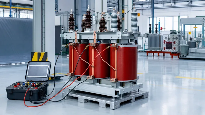
Liquid-filled units utilise mineral oil, synthetic ester, or natural ester to provide electrical insulation and convective heat removal. They feature superior self-healing properties under minor transient discharges and offer lower upfront capital expenditure. However, they require bunding (oil containment catchments) and strict fire separation barriers under NFPA 850 or local building codes. Conversely, cast resin units employ epoxy resin reinforced with quartz or glass roving under vacuum (Class F or Class H insulation, rated for 155°C or 180°C hot-spot temperatures). Cast resin units are non-flammable and self-extinguishing, making them the standard choice for indoor electrical rooms, underground vaults, and offshore installations. To evaluate dry-type construction details thoroughly, read our dry-type transformer guide.
| Engineering Parameter | Cast Resin Dry-Type | Oil-Immersed (Mineral Oil) | Synthetic / Natural Ester |
|---|---|---|---|
| Rated Power Range | 15 kVA – 1,000 kVA | 15 kVA – 1,000 kVA | 15 kVA – 1,000 kVA |
| Maximum Voltage Class | Up to 36 kV | Up to 36 kV (and higher) | Up to 36 kV |
| BIL Capability (at 33 kV) | 170 kV peak | 170 kV – 200 kV peak | 170 kV – 200 kV peak |
| Fire Risk & Classification | F1 fire behaviour (self-extinguishing) | Class O1 (combustible, flashpoint ~140°C) | Less-flammable fluid class (flashpoint >300°C) |
| Maintenance Requirement | Minimal (periodic vacuuming/dust check) | Oil sampling, DGA, moisture checks | Periodic moisture & fluid sampling |
| Installation Location | Indoor plants, basements, tunnels | Outdoor yards, bunded substations | Indoor or sensitive eco-zones |
| Relative Capital Cost | 1.25 – 1.45× baseline | 1.0× (Baseline benchmark) | 1.30 – 1.50× baseline |
Applications for a high voltage step up transformer in compact setups
A high voltage step up transformer in lower power ratings is engineered to elevate standard low voltages (such as 400 V, 480 V, or 690 V) to distribution voltages (6.6 kV, 11 kV, 22 kV, or 33 kV) for small-scale generation or isolation test systems.
Deploying a small transformer in step-up mode differs fundamentally from standard distribution step-down duties. The windings must accommodate reverse power flow, which alters the magnetic excitation and voltage drop characteristics. When energised from the low-voltage winding, the transformer draws significantly higher inrush current relative to its rated full-load current—frequently 10 to 14 times rated amperes—due to the inner winding being closer to the magnetic core limb. If the low-voltage source possesses high source impedance (such as a remote diesel generator or small hydro plant), this intense inrush current causes severe voltage dip, potentially tripping generator protection relays.
Critical applications include:
- Small-Scale Renewable Integration: Interfacing small hydro-turbines, biogas gensets, or localised solar PV arrays to utility medium-voltage distribution networks.
- High-Voltage Test Benches: Supplying variable medium-to-high voltage for factory insulation testing, cable hipot checks, and switchgear qualification.
- Long-Distance Motor Feeders: Stepping up 400 V or 690 V to 3.3 kV or 6.6 kV to feed deep-well submersible pumps or remote mining pumps, offsetting line drop losses over several kilometres before stepping down at the motor terminal.
Procurement checklist: step-by-step process to buy small high voltage transformer units
Executing a structured procurement process prevents costly design iterations, shipping delays, and factory non-conformances during acceptance testing.
- Compile the Functional Specification Sheet: Document continuous kVA, primary/secondary voltages, tap configurations, vector group, system earthing arrangement (solid, low-resistance, or isolated neutral), and installation altitude (derating is mandatory above 1,000 metres above sea level).
- Establish Loss Capitalisation Parameters: Include 'A' and 'B' loss evaluation factors in the tender document. Factor A penalises no-load (core) losses over the 25-year asset lifecycle, while Factor B penalises load (winding copper) losses, ensuring suppliers do not quote cheap, loss-heavy core steel.
- Audit Factory Quality and Standards Compliance: Verify that the manufacturer operates an audited ISO 9001 facility capable of producing units adhering to IEC 60076, IEEE C57.12.00, or EN 50588-1 (EU Ecodesign Tier 2 loss mandates).
- Review General Arrangement (GA) and Bushing Terminations: Specify whether high-voltage connections require standard porcelain outdoor bushings, screened separable connectors (elbows per EN 50181 Type A/B/C), or air-insulated cable boxes to match site cable sizes.
- Witness Factory Acceptance Testing (FAT): Mandate routine tests per IEC 60076-1, including winding resistance measurement, voltage ratio and vector verification, short-circuit impedance and load loss, no-load loss and excitation current, and separate-source AC dielectric withstand tests.
- Inspect Corrosion Protection and Ingress Protection: For outdoor installations, specify minimum high-durability marine-grade paint coatings (ISO 12944) and an enclosure rating of IP54 or higher for auxiliary marshalling and cable boxes.
Common sourcing pitfalls and quality verification
The most frequent sourcing error in small high voltage transformers is failing to evaluate partial discharge levels and insulation temperature rise under non-linear harmonic loading.
Small high voltage units operating near drives, inverters, or test supplies endure elevated harmonic currents (THDi). Harmonics cause eddy current losses in the windings to surge proportional to the square of the harmonic frequency ($I_h^2 \times f_h^2$). Without specifying an adequate K-factor (such as K-4 or K-13 per IEEE C57.110), the unit will experience thermal runaway and premature insulation failure. Furthermore, on cast-resin units, insist on a partial discharge (PD) test report showing values below 10 pC at 1.3 times rated voltage per IEC 60076-11; elevated PD levels inside cast coils indicate internal micro-voids that inevitably lead to inter-turn dielectric breakdown.
Next steps: specifying and sourcing
When preparing to order, submit a comprehensive single-line diagram (SLD), ambient site conditions, preferred vector group, and terminal connection styles. Our engineering team reviews bespoke parameters to manufacture both cast resin dry-type transformers and oil-immersed transformers engineered to international standards. For specialised substation integration, examine our turnkey power transformer solutions. Submit your project requirements via our transformer quotation portal or consult directly via our engineering contact page to receive a fully dimensioned technical tender and loss evaluation within 48 hours.
Frequently asked questions
What is the typical lead time when you buy a small high voltage transformer?
Typical factory manufacturing lead times range from 6 to 12 weeks depending on the kVA rating, voltage class, and customisation. Standard stock distribution ratings can occasionally be sourced in 2 to 4 weeks, whereas units requiring special tapping ranges, synthetic esters, or seismic certifications require comprehensive factory scheduling.
Can a standard step-down transformer be wired as a high voltage step up transformer?
Yes, standard transformers can physically step up voltage in reverse, but doing so without factory derating introduces risks. The core may experience elevated flux density leading to overexcitation, and high inrush currents can trip upstream low-voltage circuit breakers unless the primary taps and winding turns ratios are properly engineered for reverse excitation.
What is the minimum BIL required for a 33 kV high voltage transformer?
Per IEC 60076-3, the standard Basic Impulse Insulation Level for a 33 kV (36 kV highest system voltage) winding is 170 kV peak. Under IEEE/ANSI standards, 34.5 kV systems frequently specify a BIL of 150 kV or 200 kV peak depending on the application and local lightning arrester coordination.
Which insulation type is preferred for indoor commercial installations?
Cast resin dry-type transformers are preferred for indoor installations because they contain zero combustible dielectric liquids, eliminate the need for concrete oil containment bunds, and carry an F1 fire classification signifying self-extinguishing operation with minimal toxic smoke emissions.
How does altitude impact the specification of high voltage transformers?
At altitudes exceeding 1,000 metres above sea level, reduced air density impairs cooling efficiency and lowers external dielectric withstand across bushings. Transformers must be specified with derated thermal capacity and increased external bushing creepage distances per IEC 60076-1 guidelines.
Tags: small high voltage transformer high voltage step up transformer transformer procurement dry type transformer distribution transformer