Key takeaways
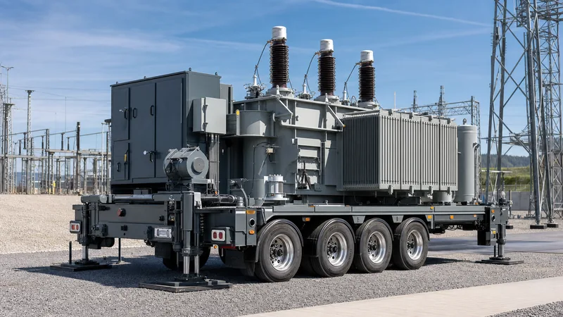
- A mobile transformer is a high-density, trailer-mounted or skid-mounted power transformer engineered for rapid grid deployment, planned maintenance bypasses, and emergency failure response.
- Axle-load limits (typically 10 to 12 tonnes per axle) and bridge clearance envelopes dictate the use of high-temperature solid insulation (Class 200/Nomex) and synthetic esters to cut core-and-coil weight by up to 25%.
- Dual- or multi-voltage primary and secondary winding configurations allow a single mobile transformer to substitute for dozens of regional substation ratings.
- Dynamic mechanical forces experienced during road transit require internal core-and-coil clamping designed to withstand continuous 3G longitudinal, 2G lateral, and 2G vertical shock loads.
- Comprehensive factory acceptance testing under IEC 60076-1 and IEEE C57.12.00 must include multi-tap dielectric tests and post-transit impact recorder analyses prior to energisation.
Quick answer: A mobile transformer is a fully transportable, self-contained power transformer engineered on a road-compliant semi-trailer or structural skid to provide rapid temporary power during catastrophic failures, scheduled substation overhauls, or delayed renewable grid tie-ins. Ratings typically span 5 MVA to 60 MVA at primary voltages up to 230 kV.
Substation asset managers and engineering, procurement, and construction (EPC) contractors increasingly rely on mobile equipment to maintain high network availability metrics (SAIDI and SAIFI). Integrating multi-voltage windings and advanced thermal insulation enables one mobile transformer to back up multiple substations across an entire utility territory or large renewable development zone.
Core Applications: Grid Support to Renewable Energy Integration
A mobile transformer serves three primary operational functions: emergency outage response, planned maintenance substitution, and interim generation grid tie-in. When a base-station power unit experiences internal arcing or insulation breakdown, deploying a transportable unit restores critical distribution feeders within 12 to 36 hours, bypassing weeks or months of typical factory replacement lead times.
During scheduled maintenance on primary switchgear, tap changers, or structural busbars, the mobile unit temporarily takes over the substation load. This eliminates the need for expensive, high-risk network back-feeding schemes. Furthermore, in large wind farms and utility solar facilities, delays in permanent substation energisation can penalise developers. As detailed in our guide to the grid integration of renewable energy sources, a road-ready mobile transformer provides immediate early generation export, allowing project developers to monetise power weeks ahead of final commercial operation dates.
For turnkey utility operations requiring integrated switchgear and control protection on the same trailer chassis, engineers often deploy an all-in-one assembly as explored in our mobile substation engineering guide.
Mobile Transformer Engineering: Weight, Clearance, and Cooling Optimisation
The core design challenge of a mobile transformer is achieving the highest possible megavolt-ampere (MVA) rating within legal road transit weights and dimensional clearance profiles. Most highway transit authorities enforce a gross vehicle weight limit and restrict individual axle loads to between 10 and 12 metric tonnes, while total vehicle height must generally stay under 4.3 metres to clear motorway overpasses.
To overcome these physical boundaries without derating capacity, experienced mobile transformer manufacturers replace standard mineral oil and cellulose systems with high-temperature insulation materials, such as aramid paper (Class 200) paired with synthetic or natural ester dielectric fluids. Under IEC 60076-14, this combination allows winding average temperature rises up to 95 K or 115 K (compared to the conventional 65 K limit in IEC 60076-2), cutting core-and-coil active steel and copper mass by 20% to 30%.
Cooling systems also diverge from standard utility practices. Instead of bulky, passive radiators (ONAN), mobile designs use forced-oil, forced-air (OFAF or ODAF) or directed water/air compact heat exchangers. Compact plate-type or finned-tube radiators mounted directly against the trailer gooseneck deliver high heat rejection while keeping overall shipping widths within standard 2.5 to 3.0-metre road vehicle envelopes.
Worked Engineering Calculation: Weight & Clearance Sizing for 40 MVA
Calculating total permissible active mass is the starting point for every mobile transformer design project. Below is an engineering calculation sizing a 40 MVA, 115 kV / 13.8 kV mobile unit for a target maximum axle loading of 11.5 tonnes on a 6-axle specialised trailer.
Design Constraints:
- Trailer tare weight (including outriggers, jacks, and towing neck): 18,000 kg
- Auxiliary gear, cable reels, and control panels: 3,500 kg
- Target axle arrangement: 6 axles at 11,500 kg/axle = 69,000 kg maximum bogie load
- Tractor fifth-wheel kingpin rating: 22,000 kg
- Total permissible gross road weight: 69,000 kg + 22,000 kg = 91,000 kg
Permissible Transformer Wet Mass:
Mmax_transformer = Mgross - (Mtrailer + Maux) = 91,000 kg - (18,000 kg + 3,500 kg) = 69,500 kg.
Thermal Up-rating Calculation:
A conventional 40 MVA, 115 kV unit with Class A cellulose (65 K rise) has a core-and-coil dry weight of approximately 42,000 kg, oil mass of 22,000 kg, and tank weight of 14,000 kg, giving a total wet mass of 78,000 kg—exceeding road limits by 8,500 kg.
By shifting to aramid insulation and an ODAF cooling regime per IEC 60076-14:
- Active core-and-coil mass reduces by 22% via higher current density (up to 4.2 A/mm2): 42,000 kg × 0.78 = 32,760 kg.
- Compact tank volume drops total dielectric fluid volume by 25%: 22,000 kg × 0.75 = 16,500 kg.
- Optimised corrugated high-tensile steel tank mass: 11,800 kg.
- Final wet transformer weight: 32,760 kg + 16,500 kg + 11,800 kg = 61,060 kg.
This configuration falls 8,440 kg below the 69,500 kg maximum limit, leaving ample safety margin for transport fluid management and on-board high-voltage terminations.
Multi-Voltage Windings and Tap Changer Flexibility
A mobile transformer achieves return on investment through fleet versatility, requiring the unit to connect seamlessly to multiple transmission and distribution voltage classes. Engineers specify series-parallel winding arrangements on both the primary and secondary circuits, configured using externally operated, de-energised multi-voltage selection switches.
For example, a dual-voltage high-voltage winding can be reconnected externally between 110 kV star and 66 kV star, while the low-voltage winding provides reconnectable links for 33 kV, 22 kV, and 11 kV operation. Designing these arrangements demands rigorous impedance matching across all link combinations to satisfy the short-circuit current withstand limits defined in IEC 60076-5.
Voltage regulation is handled by on-tank tap changers. While de-energised tap changers (DETC) save significant mass and mechanical complexity, critical utility nodes often demand regulation under dynamic system swing conditions. In such cases, lightweight vacuum-type equipment is installed as covered in our load tap changer engineering guide, ensuring tight voltage control during prolonged emergency tie-ins.
Technical Comparison: Mobile vs Fixed Substation Transformers
The structural, thermal, and electrical trade-offs between mobile power units and conventional permanent units govern where and how each asset is deployed across modern power networks.
| Engineering Parameter | Mobile Transformer | Permanent Substation Transformer | Design Impact / Rationale |
|---|---|---|---|
| Cooling Configuration | ODAF / OFAF forced circulation | ONAN / ONAF natural convection | Eliminates heavy passive radiators to compress road footprint. |
| Insulation Thermal Class | Class 200 (Aramid / Ester) | Class 105 (Cellulose / Mineral Oil) | Enables higher allowable temperature rise (Δθ = 95–115 K) to cut core size. |
| Impedance Variation (%Z) | Tolerates 7.0% to 14.0% across multi-tap taps | Strict single-value design (e.g., 8.0% ± 10%) | Multi-tap arrangements must limit fault currents across variable line voltages. |
| Mechanical Withstand | Continuous 3G shock profile (road certified) | Static seismic only (IEEE 693 0.5G typical) | Requires internal structural cross-bracing and locked core clamping frames. |
| Deployment Timeline | 4 to 12 hours once positioned on site | 3 to 8 weeks civil works and rigging | Plug-in separable connectors and on-chassis surge arresters allow rapid tie-in. |
| Operating Lifetime | 25 to 30 years (intermittent duty) | 40 to 50 years (continuous duty) | Periodic deployment cycles mean cumulative thermal ageing is spread across decades. |
Transport Constraints and Factory Acceptance Testing
Dynamic transport stresses represent the leading cause of internal core shifting and winding insulation scuffing in mobile units. Standard substation power units experience mechanical transit once or twice during their operational lifetime, whereas a mobile transformer encounters thousands of kilometres of road transit over unpaved access paths and arterial highways.
To prevent displacement of the core legs or winding blocks, mobile units feature high-strength internal cross-bracing and high-tensile clamping rods torqued to verify withstand against 3G longitudinal, 2G lateral, and 2G vertical accelerations per IEEE C57.12.00 Table 5. Every unit is fitted with calibrated, GPS-enabled 3-axis transit shock data loggers that continuously record acceleration amplitudes during road movements.
Factory acceptance testing must verify mechanical and dielectric integrity through an expanded regimen. As outlined in our guide to power transformer testing, testing protocols must be performed across every voltage combination and switch position:
- Frequency response analysis (FRA) per IEC 60076-18 to establish the baseline mechanical signature prior to factory release.
- Full dielectric testing: Lightning impulse (BIL), separate source AC withstand, and induced overvoltage with partial discharge (PD) monitoring across all high- and low-voltage tap links.
- Temperature rise testing on the lowest-voltage, highest-current connection to confirm ODAF/OFAF thermal limits under worst-case loading.
- Sound level verification per IEC 60076-10, crucial because mobile units frequently operate near populated residential zones during emergency feeder replacements.
Evaluating Mobile Transformer Manufacturers: RFQ Specification Checklist
When issuing an RFQ to prospective mobile transformer manufacturers, procurement teams must look beyond general power ratings. Sourcing teams should require suppliers to substantiate trailer integration capabilities, modular termination options, and dielectric boundary designs.
Ensure your procurement specification packet addresses these fundamental engineering questions:
- Chassis and transport homologation: Does the chassis comply with local axle-spacing regulations, steering geometry, bridge clearance envelopes, and braking directives (e.g., DOT, UNECE, or Australian ADR)?
- Bushing and termination architecture: Are high-voltage bushings fixed, pivoting, or plug-in inner-cone types? Pivoting or horizontally stowed plug-in bushings save up to 1.5 metres of overhead transit height without draining the fluid reservoir.
- Surge arrester mounting: Are station-class surge arresters mounted directly onto the trailer frame adjacent to the bushings, with ground bus links bonded to the primary chassis earth?
- Auxiliary power redundancy: Does the trailer incorporate an on-board auxiliary distribution transformer, automatic transfer switch (ATS), and backup diesel generator or battery system to power cooling pumps, fans, and tap changers independently?
- Secondary protection interface: Does the control house integration provide fibre-optic SCADA handshakes, multi-ratio CT wiring boxes, and micro-processor relay protection packages calibrated for varied grid tie-in impedances?
Next steps: specifying and sourcing
Specifying a custom mobile transformer requires balancing strict highway weight constraints against operational electrical requirements. Whether deploying units for temporary utility substation relief or commissioning large-scale renewable generation, our factory engineering team manufactures robust systems tailored to IEC, ANSI/IEEE, and national transport codes.
To get started, explore our factory-tested power transformer solutions, discover our complete multi-bay transformer substation systems, or consult directly with our engineering department through our engineering contact portal. You can also submit your detailed design brief via our online transformer quotation request form for an immediate review of weight budgets, electrical single-lines, and trailer layouts.
Frequently asked questions
What is the typical capacity of a mobile transformer?
A mobile transformer typically ranges from 5 MVA to 60 MVA, with high-voltage primary ratings spanning 33 kV up to 230 kV. Total capacity is fundamentally limited by highway transport regulations, which enforce strict axle loadings and road clearance dimensions.
How does a mobile transformer differ from a mobile substation?
A mobile transformer consists solely of the transformer unit, cooling equipment, and basic tap-changing gear mounted on a trailer. A mobile substation includes the transformer alongside trailer-mounted high-voltage circuit breakers, disconnectors, surge arresters, current transformers, and an integrated medium-voltage switchgear control house.
What cooling methods do mobile transformers use?
Mobile units predominantly use forced-oil forced-air (OFAF) or directed-oil forced-air (ODAF) cooling. These active heat exchange systems compress radiator size compared to the bulky natural-convection (ONAN) radiator banks standard on permanent substation transformers.
How are transport shock and vibrations mitigated in a mobile transformer?
Mobile units incorporate heavy-duty internal tie-rods, reinforced clamping frames, and structural perimeter tank bracing designed to withstand continuous 3G longitudinal and 2G vertical shocks. Trailers also employ air-ride suspensions and hydraulic leveling outriggers to insulate the active core during transit and energisation.
Why do mobile transformer manufacturers use ester fluids or high-temperature insulation?
Using high-temperature aramid insulation and synthetic or natural ester fluids allows the transformer to operate at higher temperature rises (up to 115 K rise). This reduces the core-and-coil mass and tank oil volume by up to 30%, keeping total gross weight within highway limits.
How fast can a mobile transformer be deployed on site?
A modern mobile transformer equipped with plug-in inner-cone terminations or pre-fitted pivoting bushings can be positioned, levelled on hydraulic outriggers, grounded, and energised within 4 to 12 hours of arriving at a prepared substation pad.
Tags: mobile transformer mobile transformer manufacturers power transformer substation engineering temporary power