Key takeaways
- Data center power distribution cascades medium-voltage utility feeds (typically 11 kV to 33 kV) down to low-voltage utilisation levels (415 V or 400 V three-phase) via dedicated isolation and distribution transformers.
- System redundancy classifications under Uptime Institute Tier standards dictate whether electrical architectures deploy N+1 concurrent maintenance or 2N fault-tolerant dual-path configurations.
- Harmonic currents from non-linear IT switched-mode power supplies necessitate transformers rated for K-factor loadings (minimum K-13 to K-20) to prevent neutral conductor overheating and core saturation.
- Power Distribution Units (PDUs) step down secondary voltages to 400 V/230 V while isolating sensitive server circuits and providing branch-circuit energy monitoring.
- Total transformer sizing must incorporate the anticipated IT floor load, critical mechanical cooling loads, uninterruptible power supply (UPS) operational efficiency losses, and a 20% to 25% future growth margin.
Quick answer: Data center power distribution is the multi-stage electrical network that takes raw medium-voltage utility power, conditions it through uninterruptible power supplies, and steps it down safely to rack-level utilisation voltages (415 V/240 V or 400 V/230 V) to maintain uninterrupted IT server operation under 2N or N+1 redundancy architectures.
Designing an effective data center power supply requires synchronising medium-voltage (MV) intake gear, backup diesel or battery generators, centralised uninterruptible power supply (UPS) systems, and remote power panels. Modern computational facilities require high operational availability, strict harmonic mitigation, and rigorous energy accounting to achieve targeted Power Usage Effectiveness (PUE) metrics. This technical guide reviews the equipment hierarchy, fault-tolerant topologies, and physical equipment sizing necessary for medium-to-hyperscale facilities.
How Are Data Centers Powered?
Data centers are powered through a cascading electrical infrastructure that converts high-reliability grid feeds into conditioned, low-voltage power backed by autonomous energy reserves. The incoming utility feed typically enters the facility boundary at 11 kV, 22 kV, or 33 kV via dual-feed ring arrangements or independent radial feeds. To inspect distribution topologies across utility interconnections, consult our analysis on radial feed vs loop feed architectures.
The power path follows a defined, five-stage progression from utility entry to the server silicon:
- Utility Ingress and MV Switchgear: High-voltage or medium-voltage feeds terminate in gas-insulated switchgear (GIS) or air-insulated metal-clad switchgear equipped with vacuum circuit breakers conforming to IEC 62271-200.
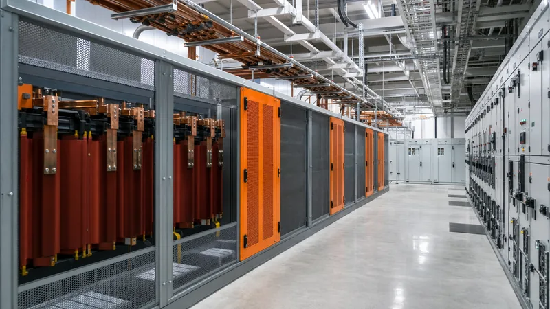
- Step-Down Substation Transformers: Liquid-immersed or cast-resin dry-type transformers step down the medium-voltage supply to low-voltage utilisation levels, typically 400 V or 415 V three-phase line-to-line. Facilities often specify integrated packages detailed in our unit substation engineering guide.
- Centralised Power Conditioning (UPS & BESS): Double-conversion online UPS modules rectify incoming alternating current (AC) to direct current (DC) to charge battery banks, then invert DC back to conditioned AC, isolating downstream loads from voltage sags, surges, and frequency fluctuations.
- Secondary Distribution (PDU and Busway): Low-voltage switchboards distribute power via overhead track busways or floor-standing Power Distribution Units (PDUs) containing isolation transformers that derive clean local neutrals.
- Rack-Level Distribution: Rack Power Distribution Units (rPDUs) divide three-phase or single-phase feeds into individual IEC 60320 C13/C19 outlets serving dual-corded server supplies.
Data Center Electrical Design: Comparing Redundancy Topologies
Data center electrical design topologies balance upfront capital expenditure against the operational risk of computational downtime. Engineers design these power distribution systems around defined availability tiers established by the Uptime Institute (Tier I through Tier IV) or EN 50600 classifications. Selecting an architecture determines the routing of busways, switchboards, and reserve power paths.
The three predominant topologies utilised in enterprise and colocation facilities feature distinct single-point-of-failure vulnerabilities, as outlined in the following engineering criteria matrix:
| Architecture Topology | Redundancy Factor | Concurrent Maintainability | Active Paths to Load | Capital Cost Multiplier | Common Application |
|---|---|---|---|---|---|
| N+1 Distributed | Modular Reserve (+1 unit) | No (maintenance drops redundancy) | Single active path | 1.0x (Baseline) | Edge computing, Tier II facilities |
| 2N (System + System) | 100% Component & Path Redundancy | Yes (no load interruption) | Two concurrent active paths | 1.8x – 2.1x | Tier III/IV enterprise & colocation |
| 2(N+1) Isolated Redundant | 100% Path + Modular Reserve | Yes (complete fault containment) | Dual active independent feeds | 2.3x – 2.6x | Mission-critical financial & defence clouds |
Under a 2N architecture, every IT cabinet receives two independent feeds (Feed A and Feed B) supplied by separate utility transformers, UPS trains, and low-voltage switchboards compliant with IEC 61439 low-voltage switchgear assemblies. Each server contains dual power supplies that draw balanced current across both rails under normal conditions; if Rail A collapses, the internal server power supply transfers 100% of the load to Rail B without phase interruption.
Critical Data Center Power Equipment and Infrastructure
Data center power equipment encompasses the protective devices, isolation transformers, power converters, and conductors situated between the incoming substation and the rack power strip. Each apparatus must withstand severe fault levels and thermal stresses caused by non-linear electronic loads.
The primary equipment classifications include:
- Cast-Resin Dry-Type Transformers: Installed inside building envelopes, these units feature Class F or H insulation systems (up to 180 °C limits). They eliminate fire and chemical containment risks associated with combustible oils.
- Power Distribution Units (PDUs): Freestanding enclosures housing main input breakers, isolation transformers with electrostatically shielded windings, panelboards, and intelligent metering units capable of monitoring branch-circuit power metrics over Modbus or SNMP protocols.
- Overhead Busway Systems: Modular busbar trunking installed directly above server racks, rated from 250 A to 800 A, allowing plug-in tap-off boxes to be positioned dynamically as cabinet densities scale.
- Automatic Transfer Switches (ATS) & Static Transfer Switches (STS): ATS units handle break-before-make transitions between utility and backup generators within 50 to 100 milliseconds, whereas solid-state silicon-controlled rectifier (SCR) STS modules execute sub-cycle source transfers within 4 milliseconds.
For large campus sites, primary medium-voltage intake gear and transformers are frequently packaged within prefabricated enclosures. Engineers can review design considerations for these systems in our guide to transformer substations and associated switchgear lines.
Sizing Data Center Power Distribution: Worked Engineering Example
Sizing the power systems for data centers requires aggregating the white space IT load, applying mechanical cooling derating factors, accounting for conversion losses, and sizing the upstream step-down transformers accordingly. The following calculation demonstrates transformer sizing for a 2.0 MW critical IT load data hall.
Step 1: Calculate the Total Facility Load
- Critical IT Load ($P_{IT}$): 2,000 kW
- Target Power Usage Effectiveness (PUE): 1.35
- Total Facility Power ($P_{Total}$) = $P_{IT} \times \text{PUE} = 2,000 \times 1.35 = 2,700 \text{ kW}$
Step 2: Determine Apparent Power (kVA)
Assuming an overall facility operating power factor ($ ext{PF}$) of 0.95 lagging:
$$\text{Total Apparent Power } (S) = \frac{P_{Total}}{\text{PF}} = \frac{2,700 \text{ kW}}{0.95} = 2,842.1 \text{ kVA}$$
Step 3: Account for 2N Architecture and Redundancy Loading
In a true 2N redundant distribution scheme, two identical transformer strings share this load. Under normal operation, each transformer operates at a maximum of 50% capacity. To prevent overloading during an emergency failover (where one unit assumes the entire 2,842.1 kVA load) and to include a 20% engineering headroom for future IT expansion:
$$\text{Design Capacity per Transformer} = \frac{S}{\text{Target Maximum Load Ratio}} \times \text{Growth Factor} = \frac{2,842.1 \text{ kVA}}{0.80} \times 1.20 = 4,263 \text{ kVA}$$
Step 4: Standard Unit Selection
Select the next standard rating under IEC 60076 standards. For this application, specify two identical 4,500 kVA (or two dual-fed 2,500 kVA units per half-hall) cast-resin dry-type transformers configured with 6.0% to 7.5% impedance voltage (%Z) to manage prospective fault currents within standard switchgear interrupting limits (typically 50 kA or 65 kA at 400 V).
Harmonic Mitigation and Transformer Selection for Data Centers
Non-linear power supplies inside server racks generate rich triplen harmonic currents (specifically the 3rd, 9th, and 15th harmonics) that summate constructively on the neutral conductor rather than cancelling out. Without appropriate design adaptations, these harmonic currents cause severe eddy-current losses, stray load heating in core steel, and neutral conductor burnouts. For complete transformer sizing formulas and harmonic deratings, review our dedicated transformers for data centers guide.
Standard distribution transformers built to general commercial specifications will overheat when subjected to data center load profiles with high Total Harmonic Distortion for Current ($THD_i$). When specifying dry-type transformers for PDU integration or white-space distribution, engineers must apply specific harmonic mitigation measures:
- K-Factor Rating: Specify units compliant with ANSI/IEEE C57.110. A rating of K-13 is the industry baseline for standard densities; high-density high-performance computing (HPC) environments running dense graphics processing unit (GPU) clusters require K-20 ratings.
- Neutral Conductor Sizing: Neutral busbars and incoming neutral cables must be rated to 200% of the phase conductor cross-sectional area to carry unbalanced triplen return currents safely.
- Electrostatic Shielding: Continuous copper shields placed between the primary and secondary windings attenuate common-mode high-frequency electrical noise and switching transients originated by power electronic switches.
- Core Flux Density Derating: Core designs must operate at lower peak flux densities (typically 1.45 to 1.55 Tesla instead of 1.7 Tesla) to prevent core saturation during sustained harmonic voltage distortion.
Next steps: specifying and sourcing
When preparing procurement documentation or a formal Request for Quotation (RFQ) for data center power equipment, precise technical scoping prevents project schedule delays and field retrofits. Ensure your enquiry package contains the specified load profile, expected harmonic spectrum, required impedance voltage (%Z), operating ambient temperatures, and enclosure protection ratings (such as IP21 or IP31 for indoor white space, or IP54 for outdoor modules).
Our factory manufactures factory-tested dry-type transformers, liquid-immersed units, and fully integrated HV/LV switchgear designed for modern critical facilities. Direct your technical single-line diagrams (SLDs) and engineering specifications to our team via the request a quote page to obtain full design sheets, loss figures, and factory acceptance schedules.
Frequently asked questions
how are data centers powered
Data centers are powered through a tiered system taking high- or medium-voltage electricity from utility substations, stepping it down through distribution transformers, conditioning it via uninterruptible power supplies (UPS), and distributing it through low-voltage switchboards and power distribution units (PDUs) to server racks.
What is the difference between N+1 and 2N data center power distribution?
An N+1 topology provides one extra component (such as an additional UPS or transformer) to support the base system capacity, while a 2N topology provides a completely duplicated, independent distribution path from utility to server, ensuring zero downtime if one full path fails.
Why do data centers require K-factor rated transformers?
Data centers require K-factor rated transformers because IT server power supplies generate non-linear harmonic currents that cause severe eddy-current and stray heating in standard transformer windings, risking thermal failure unless engineered to handle these harmonic loads.
What voltage levels are used in data center power distribution?
Medium-voltage incoming utility feeds typically operate between 11 kV and 33 kV, which are stepped down to 400 V or 415 V three-phase for low-voltage switchboards and busways, delivering 230 V or 240 V line-to-neutral power at the server rack level.
What is the role of a PDU in a data center?
A Power Distribution Unit (PDU) steps down or isolates distribution voltage, controls branch circuit protection, filters electrical noise, establishes a local grounding reference, and measures real-time circuit power consumption across the server room.
Tags: data center power distribution data center electrical design data center power equipment data center power supply data center power systems


