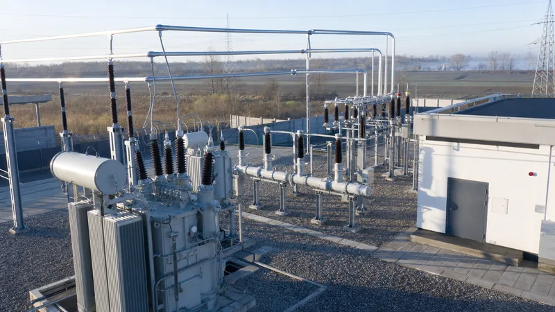
Key takeaways
- An electric substation functions as an active node in power networks to transform voltage levels, route power flows, and isolate faults.
- Transmission substations handle bulk power stepping from 110 kV up to 765 kV, whereas electrical distribution substations step voltages down to medium-voltage distribution levels between 11 kV and 33 kV.
- Core electrical substation equipment includes power transformers, circuit breakers, disconnect switches, instrument transformers, and surge arresters arranged in defined busbar configurations.
- Transformer short-circuit impedance (%Z) directly governs the downstream fault level, dictating the required symmetrical breaking capacity of medium-voltage switchgear under IEC 62271-100.
- Substation topologies range from cost-effective Air-Insulated Substations (AIS) to space-saving Gas-Insulated Substations (GIS) and prefabricated compact unit substations certified to IEC 62271-202.
Quick answer: An electric substation is a critical node in an electrical generation, transmission, and distribution network designed to transform voltage levels, switch transmission circuits, isolate network faults, and control the flow of electrical power. Using power transformers, switchgear, protective relays, and busbar arrangements, substations step voltages up for efficient long-distance transmission or step them down for industrial and municipal distribution.
Modern utility and industrial networks rely on precisely engineered substations to maintain system stability, enforce fault ride-through capabilities, and deliver compliant power quality. Whether stepping down 110 kV bulk power for a manufacturing campus or integrating multi-megawatt renewable generation assets, the design of an electric substation determines total operational efficiency, short-circuit withstand capabilities, and life-cycle reliability across decades of operation.
What is an electric substation and how does it work?
To define electrical substation functionality: it is an integrated assembly of high-voltage and medium-voltage electrical apparatus engineered to switch circuits, transform voltage ratings, and provide system protection between generation sources and end-use loads. When examining how does a power substation work, the operational principle relies on electromagnetic induction and automated circuit isolation. Alternating current enters the facility via overhead lines or underground cables, passes through protective surge arresters and disconnect switches, and enters the primary windings of a power transformer. The transformer adjusts the voltage ratio inversely proportional to the current according to Faraday's law, minimising conductor losses ($I^2R$) across regional links or reducing potentials to levels safe for facility switchboards.
Beyond transformation, the answer to how do electrical substations work centers on dynamic network management. Protective current transformers (CTs) and voltage transformers (VTs) continuously sample system parameters, sending analogue values to microprocessor-based numerical relays. As detailed in our substation protection engineering guide, if current or voltage vectors exceed pre-set thresholds—such as during a line-to-earth fault or transformer short-circuit—the protection relays trip circuit breakers within 40 to 60 milliseconds to de-energise the compromised section while maintaining power flow to adjacent healthy feeders.
Types of substations: transmission vs distribution
A power substation is classified according to its network tier, structural layout, and operating voltage class. The two primary categories in power delivery are the transmission substation and the electrical distribution substation, each serving distinct functional mandates in electrical grids.
A transmission substation operates at extra-high and high-voltage levels, typically from 110 kV up to 765 kV. Located adjacent to generating facilities or at key interconnection hubs along the transmission grid, these facilities step up generated voltage (often 11 kV to 24 kV) to transmission levels to reduce transmission current and conductor cross-sections over hundreds of kilometres. Transmission stations feature large clearance envelopes, advanced bus schemes (such as breaker-and-a-half or double-bus double-breaker), and high-capacity reactive power compensation systems, including static VAR compensators (SVC) and shunt reactors.
An electrical distribution substation operates at lower voltage classes, typically stepping down 110 kV, 66 kV, or 33 kV supply voltages to medium-voltage distribution ranges, such as 11 kV, 6.6 kV, or 415 V three-phase supply. These substations directly supply industrial zones, municipal networks, and commercial installations. Distribution facilities are frequently packaged into compact, factory-tested arrangements—such as those described in our unit substation engineering guide—to minimise footprint in dense urban environments and reduce on-site civil works.
Essential electrical substation equipment and components
Every electric substation depends on primary electrical plant to handle bulk energy transfer and secondary systems to manage control, monitoring, and fault clearing. Key electrical substation components operate as an integrated system compliant with international standards such as IEC 61936-1 and IEEE C2.
- Power transformers: The core of any transformer sub station, stepping voltage up or down using oil-immersed or cast-resin dry-type construction per IEC 60076-1. They incorporate on-load tap changers (OLTC) to regulate secondary voltage against fluctuating load profiles.
- Circuit breakers: Primary switching devices rated to interrupt both continuous full-load currents and severe prospective short-circuit currents up to 63 kA under IEC 62271-100. Modern systems use sulphur hexafluoride (SF6) puffer or vacuum interrupter technology.
- Disconnector and earthing switches: Visible-break off-load isolation mechanisms that permit safe access for maintenance personnel in accordance with IEC 62271-102.
- Instrument transformers: Highly accurate magnetic or capacitive current transformers (CTs) and potential transformers (PTs/VTs) conforming to IEC 61869-2 and IEC 61869-3, providing isolated measurement inputs to metering units and protection relays.
- Surge arresters: Metal-oxide varistor (MOV) arresters installed line-to-earth to clamp lightning impulses and switching surges, coordinated to the substation Basic Impulse Level (BIL).
- Busbar systems: Rigid aluminium tubes or flexible stranded conductors that serve as central electrical distribution points, rated to carry full system currents and withstand dynamic electromagnetic forces during peak fault events.
AIS vs GIS vs prefabricated unit substations
Selecting the structural topology of a high voltage substation involves balancing physical space constraints, capital outlay, environmental harshness, and ongoing maintenance capabilities. The three dominant construction topologies are Air-Insulated Substations (AIS), Gas-Insulated Substations (GIS), and compact prefabricated unit substations.
| Substation Topology | Footprint Requirement | Operating Voltage Range | Capital Cost Multiplier | Maintenance Interval | Applicable Standards |
|---|---|---|---|---|---|
| Air-Insulated Substation (AIS) | 100% (Baseline envelope) | 11 kV to 765 kV | 1.0x (Lowest CAPEX) | 3 to 5 years (Atmospheric cleaning) | IEC 61936-1, IEEE C37.30 |
| Gas-Insulated Substation (GIS) | 10% to 15% of AIS footprint | 66 kV to 800 kV | 1.8x to 2.5x of AIS | 10 to 15 years (Sealed chambers) | IEC 62271-203, IEEE C37.122 |
| Prefabricated Unit Substation | 15% to 25% of AIS footprint | 3.3 kV to 40.5 kV | 1.1x to 1.3x of AIS | 4 to 6 years (Enclosed MV/LV gear) | IEC 62271-202, EN 50532 |
While AIS delivers lower initial hardware costs and simple visual inspection routines, its expansive land footprint and vulnerability to coastal salt-fog or industrial airborne pollution present operational liabilities. Conversely, GIS encloses all live parts within grounded aluminium enclosures pressurised with SF6 or alternative eco-gases, delivering robust dielectric endurance in tight urban centres or offshore substations. For commercial parks and industrial distribution, fully packaged compact substations integrate medium-voltage switchgear, distribution transformers, and low-voltage switchboards inside a single transportable enclosure.
Engineering calculation: sizing and fault level analysis
Proper substation design requires calculating the prospective symmetrical short-circuit current to establish the interrupting ratings of circuit breakers and dynamic stress parameters of busbars in accordance with IEC 60909.
Consider an electrical distribution substation supplied at 33 kV with an infinite source bus, stepping down to 11 kV to supply an industrial plant. The engineering specifications are:
- Transformer rated power ($S_r$): 20 MVA (20,000 kVA)
- Primary voltage ($V_1$): 33 kV line-to-line
- Secondary voltage ($V_2$): 11 kV line-to-line
- Transformer percent impedance ($Z\%$): 10.0% ($0.10\text{ p.u.}$) on its 20 MVA base
First, calculate the secondary full-load rated current ($I_r$):
$$I_r = \frac{S_r}{\sqrt{3} \times V_2} = \frac{20{,}000\text{ kVA}}{\sqrt{3} \times 11\text{ kV}} = \frac{20{,}000}{19.0526} = 1049.7\text{ A}$$
Next, determine the prospective three-phase symmetrical short-circuit current ($I_{sc}$) on the 11 kV busbar, assuming infinite utility source capacity:
$$I_{sc} = \frac{I_r}{Z_{pu}} = \frac{1049.7\text{ A}}{0.10} = 10{,}497\text{ A} = 10.5\text{ kA}$$
The corresponding prospective short-circuit fault MVA ($S_{sc}$) is calculated as:
$$S_{sc} = \frac{S_r}{Z_{pu}} = \frac{20\text{ MVA}}{0.10} = 200\text{ MVA}$$
To select medium-voltage switchgear under IEC 62271-100, the calculated $I_{sc}$ of 10.5 kA dictates that a standard circuit breaker rated at 12 kV, 1250 A continuous, with a short-circuit breaking capacity of 16 kA or 25 kA for 3 seconds is fully compliant. If future utility network changes introduce a finite grid fault level of 1000 MVA at 33 kV, engineer the combined impedance by adding the upstream source per-unit impedance ($Z_{source} = 20 / 1000 = 0.02\text{ p.u.}$) to the transformer impedance ($0.10\text{ p.u.}$), yielding a total system impedance of $0.12\text{ p.u.}$ and reducing downstream bus fault current to 8.75 kA. You can use our kVA calculator and sizing guide to model custom load parameters.
Commissioning protocols and factory acceptance standards
A newly erected power sub station must pass rigorous field testing and pre-commissioning checks prior to energisation to guarantee operator safety and equipment longevity. Commissioning engineers execute a sequential validation programme following guidelines in our substation testing engineering guide and relevant international standards.
- Insulation resistance and polarisation index (PI): Measure core, primary, and secondary winding insulation resistance with a 5 kV DC insulation tester per IEEE C57.152, verifying a minimum PI ratio ($R_{10min} / R_{1min}$) greater than 2.0.
- Transformer turns ratio (TTR) and vector group verification: Confirm voltage ratios on all tap positions within $\pm 0.5\%$ of nameplate ratings according to IEC 60076-1 clause 10.3.
- Dielectric breakdown of insulating liquid: Draw oil samples from the transformer tank and OLTC to verify dielectric breakdown voltage exceeds 50 kV across a 2.5 mm gap per IEC 60156.
- Switchgear contact resistance and timing tests: Measure micro-ohm resistance across main vacuum or SF6 contacts and conduct breaker operating time tests (close, open, close-open) per IEC 62271-100.
- Current transformer secondary loop and polarity checks: Perform primary injection testing to confirm saturation curves, knee-point voltage, burden limits, and correct protective relay directionality.
- Earth grid integrity and step/touch potential testing: Verify earth grid resistance is under 1.0 ohm and that touch and step potentials comply with maximum allowable limits specified in IEEE 80.
Next steps: specifying and sourcing
When specifying equipment for an electric substation development, compile a complete technical schedule that includes nominal and maximum system voltages, basic impulse level (BIL), continuous and prospective short-circuit currents, transformer impedance tolerances, busbar single-line diagrams, and site environmental conditions. Explore our high-performance power transformers, modular prefabricated transformer substations, and medium-voltage HV/LV switchgear engineered to IEC and IEEE standards. Submit your single-line diagrams and tender specifications to our engineering team through our substation quotation portal to receive tailored engineering reviews, layout drawings, and factory direct commercial proposals.
Frequently asked questions
what is a substation
A substation is an operational node in an electrical grid that switches circuits, transforms voltage levels up or down, and provides protection against network faults. It uses power transformers, circuit breakers, and switchgear to link generation sources safely to industrial, commercial, and residential consumers.
what is an electrical sub station
An electrical substation is a dedicated physical facility housing electrical equipment such as transformers, busbars, circuit breakers, and protective relays. It alters alternating-current voltages between transmission lines and local distribution feeders to balance transmission efficiency with end-user safety.
what does a substation do
A substation controls the routing of electrical power, changes voltage magnitudes between high-voltage transmission and low-voltage consumption, and isolates faulted circuits within milliseconds. It also provides reactive power compensation, voltage regulation, and operational monitoring across the interconnected power grid.
what does a power substation do
A power substation regulates regional electrical flows by converting transmission voltages down to intermediate distribution levels, stabilizing grid frequency and voltage under changing loads, and protecting electrical infrastructure from short circuits, lightning strikes, and equipment overloads.
how does a power substation work
A power substation works by receiving high-voltage power through circuit breakers and disconnect switches, stepping the voltage up or down via electromagnetic induction in power transformers, and distributing the transformed power across configured busbars to outgoing feeders monitored by protection relays.
how do electrical substations work
Electrical substations work through the coordinated operation of primary power equipment and secondary automated control systems. High-voltage power passes through transformers that adjust voltage ratios, while instrument transformers feed real-time measurements to protective relays that instantly trip circuit breakers during overcurrent or earth-fault conditions.
how does substation work
A substation works by routing high-voltage alternating current from incoming transmission lines into transformers that scale voltage down to safe operational limits. Automated switchgear, busbars, and protection systems regulate current flow, prevent grid overloads, and disconnect damaged lines without interrupting the broader utility network.
Tags: electric substation power substation substation equipment distribution substation substation components


