Key takeaways
- The open circuit transformer test measures no-load core losses (hysteresis and eddy currents) and determines the shunt branch parameters (Rc and Xm) of the equivalent circuit.
- Energising the low-voltage (LV) winding while leaving the high-voltage (HV) winding open-circuit is standard practice to minimise operational voltage risks and instrumentation ratings.
- Because no-load current is typically only 1% to 3% of rated full-load current, winding I²R copper losses during the test are negligible, making measured power effectively equal to iron loss.
- Accurate test results under IEC 60076-1 clause 11.5 require correcting measured losses using average and RMS voltage readings to account for source voltage waveform distortion.
- Combining data from the oc test of transformer with the complementary short circuit test provides the complete electrical model needed for thermal, efficiency, and regulation assessments.
Quick answer: The open circuit transformer test (or no-load test) determines a transformer's core iron losses, no-load excitation current, and parallel shunt branch parameters (core-loss resistance and magnetising reactance). Conducted by applying rated voltage at rated frequency to one winding while keeping the other winding open-circuited, it reveals fixed operating losses independent of consumer load.
In electrical equipment manufacturing and substation commissioning, power losses directly impact operational expenditure, cooling design, and environmental compliance. Transformers run continuously energised across their 30-to-40-year lifespan, meaning core losses represent a non-stop energy drain from the grid. Conducting a rigorous factory transformer test ensures that core laminations, joint interleaving, and magnetic steel grade conform strictly to guaranteed efficiency figures before delivery to site.
Purpose and Principles of the Open Circuit Transformer Test
The primary purpose of an open circuit transformer test is to isolate the magnetic circuit behaviour from load-dependent winding effects. When a transformer operates without connected loads on its secondary terminals, the only current drawn from the supply is the excitation or no-load current, denoted as I₀. This excitation current comprises two distinct vectors: the active core-loss component (Ic) which accounts for real power dissipated in the magnetic core, and the reactive magnetising component (Im) required to establish magnetic flux across the core laminations.
Core losses consist of hysteresis losses and eddy current losses. Hysteresis loss occurs as magnetic domains within the cold-rolled grain-oriented (CRGO) or amorphous electrical steel reverse alignment every half-cycle. Eddy current losses result from circulating currents induced within the conductive steel sheets, mitigated by applying thin surface insulating coatings and keeping sheet thickness typically between 0.23 mm and 0.30 mm. Because the no-load current is exceptionally low—typically 0.5% to 2.5% of rated current in medium and power transformers—the ohmic losses (I²R) produced in the energised winding are microscopic and mathematically negligible. Consequently, a precision wattmeter connected during the oc test of transformer records the pure iron loss of the unit.
Test Configuration and Step-by-Step Procedure
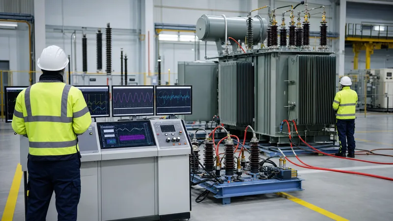
Standard test bays execute the open ckt test of transformer by supplying the low-voltage (LV) winding while leaving the high-voltage (HV) winding entirely open and un-terminated. Energising the LV side keeps the excitation voltage within manageable, readily accessible test supply limits (for instance, 400 V or 415 V rather than 11 kV or 33 kV) while maintaining safe working conditions for test engineers. However, the HV terminals remain energised at full potential via electromagnetic induction; therefore, strict terminal isolation barriers and clearance boundaries must be maintained per safety protocols.
To execute the test methodically, test bay technicians follow a sequential verification procedure:
- Safety isolating and grounding checks: Ensure the transformer tank is bonded to the main substation earth pit. Verify that HV bushings maintain statutory electrical air clearances and that protective enclosures are cleared of personnel.
- Instrumentation hook-up: Connect an adjustable three-phase (or single-phase) AC power source to the LV terminals through a variable autotransformer or frequency converter. Install precision multi-channel power analysers, current transformers (CTs), and potential transformers (PTs) calibrated in line with transformer testing equipment guidelines.
- Dual-voltmeter arrangement: Connect both an RMS-responding voltmeter and an average-responding voltmeter (scaled to RMS for a pure sine wave) across the energised terminals to monitor supply waveform purity.
- Voltage ramping: Gradually increase the applied voltage until the mean-sensing voltmeter indicates the rated line-to-line voltage (Vn) at rated frequency (typically 50 Hz or 60 Hz).
- Data logging: Record applied test voltage (V₀), excitation current per phase (I₀), active power dissipation in watts (P₀), and power supply frequency.
- De-energisation: Smoothly ramp down the test voltage regulator to zero before switching off the incoming circuit breaker and discharging residual capacitance.
Mathematical Derivations and Worked Calculation
Converting open circuit test readings into shunt branch equivalent circuit values allows design engineers to model transformer behaviour under varying operating regimes. Consider a factory test of a three-phase distribution transformer rated at 1000 kVA, 11,000 V / 415 V, 50 Hz, vector group Dyn11. The test is carried out on the 415 V delta LV winding.
The measured test bench readings at rated terminal voltage are:
- Line-to-line voltage: VLL = 415 V
- Total three-phase no-load power: P₀ = 1,650 W
- Average line excitation current: I₀ = 13.8 A
First, calculate the per-phase equivalent star parameters. The per-phase terminal voltage is:
Vph = VLL / √3 = 415 / 1.73205 = 239.6 V
The per-phase no-load power dissipation is:
P0,ph = P₀ / 3 = 1,650 / 3 = 550 W
The no-load power factor (cos φ₀) is calculated using the total three-phase power formula:
cos φ₀ = P₀ / (√3 × VLL × I₀) = 1,650 / (1.73205 × 415 × 13.8) = 1,650 / 9,919.8 = 0.1663
The corresponding phase angle and reactive power factor are:
φ₀ = arccos(0.1663) = 80.43°
sin φ₀ = sin(80.43°) = 0.9861
Next, separate the excitation current into core-loss (Ic) and magnetising (Im) components:
Ic = I₀ × cos φ₀ = 13.8 × 0.1663 = 2.295 A
Im = I₀ × sin φ₀ = 13.8 × 0.9861 = 13.608 A
Finally, calculate the parallel equivalent shunt resistance (Rc) and magnetising reactance (Xm) referred to the LV side:
Rc = Vph / Ic = 239.6 / 2.295 = 104.40 Ω
Xm = Vph / Im = 239.6 / 13.608 = 17.61 Ω
These parameter values represent the magnetic core model in simulation studies, load flow analyses, and loss verification sheets.
Comparing the Open Circuit Test and Short Circuit Test of Transformer
A full electrical profile of any transformer requires pairing the no-load evaluation with a short circuit test of transformer. While the open circuit test targets the parallel magnetising branch at rated voltage and negligible current, the transformer sc test targets series winding resistances and leakage reactances at rated full-load current and reduced voltage. The two procedures complement each other, providing the full set of parameters required to construct the transformer's equivalent circuit.
In a short ckt test of transformer, the LV terminals are solidly bridged with a low-resistance copper bar, and a low test voltage (typically 4% to 10% of rated HV voltage) is applied to the HV terminals until full rated current circulates. The table below delineates the structural differences between these two foundational routine tests:
| Characteristic | Open Circuit Transformer Test | Short Circuit Test of Transformer |
|---|---|---|
| Energised Winding | Low-Voltage (LV) winding | High-Voltage (HV) winding |
| Opposite Winding Status | Open-circuited (isolated) | Short-circuited with robust busbars |
| Applied Voltage Level | 100% rated voltage (nominal Vn) | Fractional voltage (typically 3%–10% of Vn) |
| Current Flowing | No-load current I₀ (0.5%–3% of rated) | Full rated current (100% In) |
| Primary Measurement | Core iron losses (hysteresis + eddy current) | Copper losses (winding I²R + stray losses) |
| Equivalent Parameters | Shunt branch: Core resistance (Rc), Reactance (Xm) | Series branch: Equivalent resistance (Req), Reactance (Xeq) |
| Governing Standard | IEC 60076-1 Clause 11.5 / IEEE C57.12.90 | IEC 60076-1 Clause 11.4 / IEEE C57.12.90 |
| Operating Flux Density | Full rated core flux density (1.5–1.7 Tesla) | Extremely low flux density (<0.1 Tesla) |
Combining the series parameters from the short-circuit run with the winding resistance test of transformer results yields total load losses corrected to reference temperatures (such as 75°C or 85°C).
Standards, Waveform Corrections, and Acceptance Limits
International testing standards enforce precise voltage waveform conditions during no-load loss verification. Under IEC 60076-1 clause 11.5 and IEEE C57.12.90 clause 8, harmonic distortion in the test power supply can cause substantial errors in measured core losses. Hysteresis losses depend almost entirely on peak magnetic flux density (proportional to the average rectified voltage), whereas eddy current losses depend directly on root-mean-square (RMS) voltage.
If the applied test voltage waveform is distorted by grid harmonics or non-linear supply equipment, the measured no-load loss (Pm) must be corrected to a pure sinusoidal equivalent loss (P₀) using the standard equation:
P₀ = Pm × (1 + d)
where the correction coefficient d is defined by:
d = (U' - U) / U'
Here, U' represents the voltage reading taken with an average-responding voltmeter scaled to RMS, and U represents the reading from an authentic RMS voltmeter. If the deviation between U' and U exceeds 3%, the supply waveform is considered unacceptable for compliance certification, and clean supply generators or tuned filters must be introduced. In terms of commercial tolerance, IEC 60076-1 Table 1 permits an absolute maximum deviation of +15% on declared no-load losses for a single unit, provided total combined losses (no-load plus load losses) do not exceed +10% of the guaranteed contract values.
Factory-Floor Errors and Troubleshooting During Testing
Achieving repeatable measurements during an open circuit transformer test requires eliminating measurement errors inherent to low-power-factor circuits. Because the no-load power factor is typically between 0.10 and 0.20 lagging, slight phase displacement errors within measurement instrument transformers introduce disproportionate active power reading deviations.
Practical diagnostic rules developed on the test floor include:
- Instrument transformer phase angle correction: Conventional current and voltage transformers exhibit internal phase angle errors. In circuits operating at cos φ < 0.2, a phase displacement of merely 10 minutes (0.166 degrees) can alter measured active power by 5% or more. Test laboratories must utilise Class 0.1 or 0.05 calibrated instrumentation featuring automatic phase angle digital compensation.
- Improper earthing and electrostatic pick-up: The open HV winding acts as an antenna capable of capacitive coupling with adjacent overhead busbars and factory crane structures. Leaving bushing screens ungrounded or floating induces electrostatic voltages that disturb electronic power analyser inputs.
- Residual core magnetisation: If the core underwent prior direct-current testing—such as DC winding resistance measurement or insulation resistance checks—residual remanent flux will distort initial excitation currents. Demagnetising the core using a decaying low-frequency AC source prior to the open circuit run is mandatory to prevent artificially high current readings.
- Core clamp and insulation tracking: Abnormally elevated active losses combined with humming or buzzing indicate micro-sparking across core-lamination burrs, damaged core bolt insulation, or defective tie plate grounding circuits. For oil-filled equipment, pairing unusual test results with power transformer testing methods like dissolved gas analysis (DGA) pinpoints emerging thermal hot spots before the tank is sealed.
Next steps: specifying and sourcing
When specifying high-efficiency distribution units or large power equipment, defining strict no-load loss ceilings and test protocols protects capital investments against excessive lifecycle utility costs. Include explicit requirements in your RFQ covering standard compliance (IEC 60076 or IEEE C57), core steel metallurgy (such as laser-scribed high-permeability CRGO), guaranteed sound pressure levels, and factory acceptance testing (FAT) witness inspection parameters. Explore our engineering designs for oil-immersed transformer solutions and high-specification dry-type transformer units. Submit your project requirements and loss capitalisation formulas via our quote request page or reach out to our engineering team directly through the contact page for tailored technical support.
Frequently asked questions
What is an open circuit transformer test?
An open circuit transformer test is a standard routine factory test that measures a transformer's no-load losses and excitation current at rated voltage. It determines core iron losses (hysteresis and eddy current) and identifies the shunt resistance and magnetising reactance parameters of the equivalent circuit.
Why is the open circuit test performed on the LV side?
The test is conducted on the low-voltage winding for operator safety and practical equipment sizing. Supplying rated low voltage (such as 400 V rather than 11 kV or higher) requires standard variable voltage supplies and readily available test bench instruments while producing identical core flux conditions.
Why are copper losses neglected during the open circuit test?
Copper losses are neglected because the excitation current drawn during the test is typically only 0.5% to 3% of rated full-load current. Since winding I²R losses scale with the square of the current, the power dissipated in the winding resistance is practically zero compared to core losses.
What is the difference between open circuit test and short circuit test of transformer?
The open circuit test applies rated voltage to one winding with the other open to measure core iron losses and shunt branch parameters. The short circuit test applies a reduced voltage to circulate rated current through shorted windings, measuring full-load copper losses and series leakage impedance.
How does voltage waveform distortion affect open circuit test results?
Waveform distortion skews core loss readings because hysteresis losses depend on average voltage, whereas eddy current losses depend on RMS voltage. IEC 60076-1 clause 11.5 mandates measuring both average and RMS voltages and applying a mathematical correction factor if waveform distortion is detected.
Can residual magnetism distort open circuit transformer test results?
Yes, residual DC magnetisation left from prior winding resistance tests creates magnetic asymmetry and inrush-like excitation peaks. This artificial saturation increases the apparent no-load current and loss readings, requiring magnetic core degaussing before recording official acceptance values.
Tags: open circuit transformer test short circuit test of transformer oc test of transformer core loss testing no load loss


