Key takeaways
- The winding resistance test of transformer windings serves to detect internal open circuits, shorted turns, loose terminal connections, and high-resistance tap changer contacts.
- Per IEC 60076-1 and IEEE C57.12.90, the acceptable phase-to-phase deviation for resistance of transformer windings must not exceed 2% between identical phases or from original factory baseline values.
- Accurate field measurement requires a four-wire Kelvin direct current (DC) micro-ohmmeter injecting an inspection current between 1% and 15% of rated winding current to prevent core saturation distortion and thermal drift.
- Temperature correction to standard reference bases (typically 75°C for liquid-immersed and 75°C or 120°C for dry-type units) requires using the material constant 234.5 for copper or 225 for aluminium conductors.
- Discharging and demagnetising the transformer core immediately after DC injection is mandatory to protect personnel from high-voltage inductive kickback and prevent severe inrush currents upon re-energisation.
Quick answer: A winding resistance test of transformer coils measures the direct-current (DC) resistance of primary and secondary windings to detect open circuits, loose internal terminations, shorted turns, and defective on-load tap changer contacts. Standardised under IEC 60076-1 and IEEE C57.12.90, phase-to-phase readings must typically match within 2% after temperature correction to 75°C.
Assessing the internal integrity of power and distribution assets requires repeatable, precision diagnostic techniques. The resistance of transformer coils provides a critical baseline during factory acceptance testing (FAT), post-transport inspection, routine substation maintenance, and post-fault investigations. Variations as small as 1% to 2% can reveal incipient thermal runaway in an internal terminal crimp, uneven conductor tensioning, or carbon buildup across selector switch contacts. As part of a structured assessment programme detailed in our field and factory transformer testing guide, winding resistance verification ensures that assets comply with operational heat-run models and phase-balance specifications prior to initial energisation.
Why perform a winding resistance test of transformer?
The winding resistance test of transformer coils is performed primarily to verify conductor integrity, identify internal manufacturing flaws, and establish a thermal reference for temperature-rise calculations.
During manufacturing, this routine test confirms that the internal conductors meet engineering drawings regarding wire cross-sectional area, material purity, and parallel strand arrangements. If a multi-strand conductor has broken strands within a continuous disc or helical winding, alternating current (AC) impedance tests might fail to detect it, whereas a sensitive DC resistance measurement highlights the cross-sectional reduction immediately.
In field environments, utility asset managers and EPC engineers test transformer resistance to evaluate the mechanical and electrical condition of the tap changer. Because on-load tap changers (OLTC) and de-energised tap changers (DETC) contain moving copper or silver-faced contacts, mechanical misalignments, spring fatigue, or contact pitting present as anomalous resistance spikes on specific tap positions. Furthermore, performing this test validates terminal bushing lead terminations, braze joints between winding sections, and neutral return paths. These values also form the denominator for determining $I^2R$ load losses during heat-run evaluations under IEC 60076-2.
Test standards and acceptance criteria for resistance of transformer
Acceptance criteria for the resistance of transformer windings require that phase-to-phase deviations remain within 2% and historical baseline deviations remain within 1% to 2%.
International standards define precise compliance thresholds for routine and diagnostic testing. Under IEC 60076-1 (Clause 10.2) and IEEE C57.12.90 (Clause 5), measurements across phases on the same tap position must demonstrate extreme symmetry. For star-connected windings with an accessible neutral terminal ($Y$ or $Y_n$), engineers measure resistance directly from phase to neutral ($R_{AN}$, $R_{BN}$, $R_{CN}$). For delta ($D$) or unearthed star configurations, line-to-line measurements are taken, requiring mathematical transformation to determine individual phase values.
| Transformer Class | Standard Reference | Allowed Phase Deviation | Deviation from Factory Baseline | Standard Reference Temp |
|---|---|---|---|---|
| Liquid-Immersed Distribution (≤2.5 MVA) | IEC 60076-1 / IEEE C57.12.00 | ≤ 2.0% | ≤ 2.0% | 75°C |
| Liquid-Immersed Power (>2.5 MVA) | IEC 60076-1 / IEEE C57.12.90 | ≤ 1.5% | ≤ 1.0% | 75°C |
| Dry-Type Distribution (Class F: 155°C) | IEC 60076-11 / IEEE C57.12.01 | ≤ 2.0% | ≤ 2.0% | 100°C / 120°C |
| Dry-Type Distribution (Class H: 180°C) | IEC 60076-11 / IEEE C57.12.01 | ≤ 2.0% | ≤ 2.0% | 120°C / 145°C |
Deviations greater than 2% between identical phases indicate defective joints, incorrect wire gauges, or localised damage. When comparing modern site measurements against historical factory test reports (FAT), values corrected to the baseline temperature must align within 1% to 2%. A shift exceeding 3% warrants immediate investigation before placing the equipment into service.
Test equipment and measurement methods
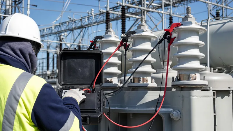
Measuring transformer winding resistance requires a four-wire Kelvin digital micro-ohmmeter equipped with dual-channel voltage sensing and inductive core saturation capability.
Because distribution and transmission windings exhibit low DC resistance—often ranging from tens of ohms on high-voltage (HV) small-capacity windings down to fractions of a milliohm ($< 0.001\,\Omega$) on low-voltage (LV) high-current windings—standard multimeters introduce massive lead resistance errors. A specialised Kelvin micro-ohmmeter separates the test lead circuit into two independent paths: one pair injects a constant direct current, while the second high-impedance pair monitors the voltage drop directly across the transformer terminals, eliminating lead and contact resistance from the calculation.
Engineers selecting instrumentation should consult modern specifications for transformer testing equipment to ensure test sets provide sufficiently high compliance voltage (typically 30 V to 50 V DC). Because a large power transformer winding represents a high inductance ($L$), current stabilisation follows an exponential time constant ($L/R$). High open-circuit compliance voltage accelerates core magnetic saturation, driving the winding into a stable resistive state within seconds rather than hours. The test current must remain above 1% of the rated winding current to guarantee accurate sensor operation, yet strictly below 15% to avoid internal Joule heating ($I^2Rt$) that causes continuous thermal drift during measurement.
Step-by-step procedure to test transformer resistance
The execution of a winding resistance test follows a strict sequence of isolation, temperature recording, direct current injection, stabilisation, and demagnetisation.
- Isolate and ground the asset: Completely isolate the transformer from all primary and secondary transmission or distribution lines, opening circuit breakers and disconnectors. Apply temporary safety grounds to discharge residual electrostatic charges before removing grounds from the specific phase under test.
- Record winding temperature: Measure the top and bottom oil temperatures on liquid-filled units, calculating the average oil temperature as the representative winding temperature if the unit has been de-energised for at least 3 to 8 hours. For dry-type transformers, record the ambient air and core surface temperature using calibrated PT100 sensors.
- Connect the Kelvin leads: Connect the current ($C_1, C_2$) and potential ($P_1, P_2$) leads of the micro-ohmmeter directly to the bushing terminals (e.g., $H_1$ to $H_2$ on HV, or $X_1$ to $X_0$ on LV). Ensure clamps grip the terminal stud firmly beneath any surface oxidation.
- Inject DC current and allow stabilisation: Initiate current injection at a selected amplitude (typically 5 A to 10 A for HV windings; 10 A to 25 A for LV windings). Monitor the digital display until the resistance reading stabilises to within three decimal places.
- Record readings across all tap changer positions: For windings with an on-load tap changer or off-circuit tap changer, test transformer resistance across every individual tap step (e.g., Tap 1 through Tap 17). Dynamic resistance measurement (DRM) profiles can simultaneously detect OLTC diverter switch transition contact open-circuits.
- Discharge the winding inductance: Stop the test and verify that the test instrument automatically dissipates stored magnetic energy through an internal discharge circuit. Never disconnect lead clamps while the discharge indicator warning is illuminated.
Temperature correction formula and calculation example
Temperature correction mathematically standardises measured winding resistance to a recognised reference base to enable direct comparison with factory baseline data.
Because the resistivity of metallic conductors rises linearly with operating temperature, a reading recorded at 18°C field ambient cannot be compared against a 75°C factory test certificate without conversion. The standard conversion equation is derived from the inferred zero-resistance temperature constant:
$$R_2 = R_1 \times \frac{T_k + T_2}{T_k + T_1}$$
Where:
- $R_2$: Calculated resistance at the reference temperature (typically 75°C for mineral oil units).
- $R_1$: Measured resistance at field test temperature.
- $T_1$: Winding temperature during field measurement (°C).
- $T_2$: Desired reference temperature (°C).
- $T_k$: Inferred absolute zero temperature constant ($234.5$ for 99.99% electrolytic copper; $225.0$ for electrical-grade aluminium).
Consider a practical engineering example: an HV copper winding on a step-down transformer yields a measured resistance ($R_1$) of $0.4120\,\Omega$ at an average tank oil temperature ($T_1$) of $22.0^\circ\text{C}$. To correct this value to the standard reference base ($T_2$) of $75.0^\circ\text{C}$:
$$R_{75} = 0.4120 \times \frac{234.5 + 75.0}{234.5 + 22.0} = 0.4120 \times \frac{309.5}{256.5} = 0.4120 \times 1.2066 = 0.4971\,\Omega$$
This normalised value of $0.4971\,\Omega$ is then inserted into analytical models such as the transformer equivalent circuit to evaluate copper losses and network impedance accurately.
Troubleshooting abnormal winding resistance results
Abnormal winding resistance readings pinpoint specific mechanical or metallurgical defects, such as contact oxidation, loose mechanical fasteners, or partial winding short circuits.
When an unexpected reading occurs, review the symptoms systematically:
- High resistance on all taps of one single phase: Usually indicates a high-resistance internal crimp, poor braze joint at the bushing lead connection, or improper torque on the internal terminal connection flags.
- Erratic resistance on specific tap changer positions: Indicates carbon filming, pitted contact tips, or weakened contact spring pressure in the selector switch or diverter switch assembly. Cycle the tap selector switch back and forth 10 times to wipe clean any light oxidation, then re-test.
- Uniformly low resistance across one phase: Suggests inter-turn short circuits. When turns within a disc short together, the total conductive length drops, reducing DC resistance while drastically increasing excitation current and exciting core losses.
- Unstable, wandering readings: Caused by measuring before the magnetic core reaches complete saturation, or by thermal convection within an uncooled, recently de-energised tank. In oil-filled assets covered in our guide to oil-filled transformers, verify that oil temperature has fully equalised before measuring.
Next steps: specifying and sourcing
When preparing procurement tenders or technical specifications for industrial, grid-scale, or renewable generation projects, specifying comprehensive routine testing ensures that equipment arrives free of manufacturing and transit defects. Specify factory winding resistance tests across all tap positions in accordance with IEC 60076-1 or IEEE C57.12.90, with witnessed test certificates required prior to dispatch. If you are developing substations or industrial facilities, explore our robust power transformers and durable oil-immersed transformers engineered for long-term thermal efficiency. For specific project design calculations, sub-station schedules, or factory testing criteria, submit your parameters through our transformer quotation page or speak with our application engineers via the contact page.
Frequently asked questions
What is the acceptable limit for transformer winding resistance test?
The maximum acceptable limit is a 2% deviation between identical phases, or a 2% deviation compared to baseline factory test values after temperature correction. For high-capacity power transformers above 100 MVA, tighter criteria of 1% phase-to-phase balance are standard under IEC 60076-1 and IEEE C57.12.90.
Why is DC used instead of AC for winding resistance testing?
Direct current (DC) is used because it eliminates inductive reactance ($X_L = 2\pi f L$) and capacitive reactance from the measurement circuit. Alternating current (AC) measures total impedance rather than pure ohmic resistance, which masks small contact defects, loose crimps, and fractured copper strands.
Why do we correct winding resistance to 75 degrees Celsius?
Winding resistance is corrected to 75°C because international standards establish this temperature as the standard operating reference for oil-immersed transformers operating under rated load. Standardising to 75°C removes ambient field temperature variables, allowing direct comparison with factory quality reports and accurate $I^2R$ load-loss calculations.
Can winding resistance testing damage a transformer?
The test will not damage the transformer if the direct current remains between 1% and 15% of rated current and proper discharge procedures are followed. However, disconnecting test leads before the stored magnetic energy in the core has fully discharged can generate lethal inductive voltage spikes that damage winding insulation.
How does winding resistance differ from insulation resistance?
Winding resistance measures the micro-ohm to ohm continuity through the metallic conductor itself using low-voltage DC. In contrast, insulation resistance measures leakage current through the dielectric paper or oil barrier between separate windings or between winding and ground, applying high voltages from 1 kV to 10 kV DC.
Tags: winding resistance test of transformer test transformer resistance resistance of transformer transformer testing IEC 60076-1


