Key takeaways
- Metal clad switchgear is defined by IEEE C37.20.2 as an assembly where all major components are isolated in grounded metal barriers with drawout circuit breakers and insulated buses.
- Under IEC 62271-200, metal clad designs fall under Loss of Service Continuity Category LSC2B with Class PM metallic partitions, ensuring adjacent compartments remain energised during breaker servicing.
- A typical 15kV switchgear line-up requires a rated maximum voltage of 15 kV, a power frequency withstand voltage of 36 kV rms for one minute, and a basic impulse insulation level (BIL) of 95 kV crest.
- Short-circuit thermal withstand ratings verify that busbars and supports endure both electromechanical peak forces (at 2.6 or 2.7 times rated rms) and thermal heating over a rated 1 to 3 second duration.
- Automated mechanical and electrical interlocks prevent racking a closed circuit breaker, closing the earthing switch on an energised bus, or opening compartment doors while primary circuits carry line voltage.
Quick answer: Metal clad switchgear is a medium-voltage electrical distribution assembly characterised by grounded sheet-metal barriers isolating all primary components into separate compartments: circuit breaker, main bus, incoming/outgoing cables, and low-voltage instruments. Operating up to 38 kV, it features fully drawout interrupting devices, automatic safety shutters, and insulated busbars to provide maximum operational safety and service continuity.
In industrial plants, utility substations, and generation facilities, selecting power distribution equipment demands an uncompromising approach to personnel safety, system reliability, and maintenance uptime. Engineers frequently weigh various medium-voltage switchgear architectures, evaluating whether standard metal-enclosed construction suffices or if true metal clad switchgear is mandatory. As detailed in our comprehensive electrical switchgear engineering guide, the mechanical architecture dictates how a facility handles faults, isolates equipment, and manages personnel safety during routine switching operations.
This technical guide covers the mechanical construction, international standard classifications, electrical ratings, protective interlocks, and testing criteria that govern modern assemblies. Drawing on practical factory-floor testing and site commissioning experience, we examine the engineering parameters required to specify, procure, and install high-reliability systems without costly project oversights.
Defining Metal Clad Switchgear: IEEE C37.20.2 vs IEC 62271-200
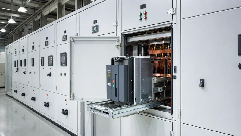
Metal clad switchgear is defined primarily by standard IEEE C37.20.2, which establishes strict compartmental and construction criteria distinguishing it from general metal-enclosed switchgear. Under North American standards, an assembly can only carry the metal-clad designation if it satisfies five strict requirements: primary interrupting devices must be completely removable (drawout); major primary circuit sections must be isolated from each other by grounded sheet-metal barriers; all live bus conductors must be fully insulated throughout; automatic mechanical shutters must close over stationary primary disconnect stabs when the breaker is removed; and mechanical or electrical interlocks must enforce safe operational sequences.
In international projects adhering to the International Electrotechnical Commission, IEC 62271-200 replaced older terminology such as 'metal-clad' and 'metal-enclosed' with performance-oriented definitions based on Loss of Service Continuity (LSC) and partition classes. A system designed to IEEE metal-clad criteria corresponds directly to an IEC LSC2B assembly featuring Class PM (metallic) partitions. LSC2B dictates that when the circuit breaker compartment is opened for servicing, both the main busbar compartment and the outgoing cable compartment can remain fully energised and functional. Class PM specifies that all internal partitions and safety shutters separating functional units are fabricated from continuous, earthed metal rather than insulating materials.
Understanding this distinction is critical for international engineering, procurement, and construction (EPC) specifications. Calling for 'metal-clad' in an IEC market without specifying LSC2B-PM and internal arc classification (IAC) can lead to receiving LSC2A or Class PI (insulating partition) equipment, which lacks the individual cable-to-breaker isolation that industrial operators require for safety during cable termination work. For a broader perspective on architectural options, review our technical comparison of ring main units vs metal-clad switchgear.
Internal Architecture and Four-Compartment Construction
The internal segregation of metal clad switchgear isolates catastrophic failures within a single functional zone, preventing arc propagation between sections. Each vertical section, or cubicle, is subdivided into four isolated chambers, separated by minimum 2.5 mm (or 11-gauge) galvanised or Aluzinc-coated sheet-steel barriers.
The four primary functional compartments include:
- Circuit Breaker Compartment: Houses the drawout vacuum or SF6 circuit breaker mounted on a precision racking truck. This chamber contains the stationary primary disconnect stabs, auxiliary control wiring plugs, and mechanical guide rails. When the truck transitions from the 'connected' to the 'test' or 'disconnected' position, mechanical linkages drive grounded steel shutters over the live stationary stabs, fully isolating the primary contacts.
- Main Busbar Compartment: Contains the continuous three-phase copper or aluminium busbars that distribute power horizontally across the switchgear line-up. In accordance with IEEE C37.20.2 Clause 5.2.2, all bus conductors are sleeved with heat-shrinkable cross-linked polyolefin insulation or fluidised-bed epoxy and supported by track-resistant cycloaliphatic epoxy or porcelain insulators. Through-bushings isolate each cubicle from its neighbour, creating segregated gas-tight or fire-resistant zones.
- Cable and Current Transformer (CT) Compartment: Provides access for incoming or outgoing medium-voltage power cables, zero-sequence CTs, standard doughnut or block-type CTs, voltage transformers (VTs), and surge arresters. Generous spatial clearance is engineered here to accommodate single-core or three-core cold-shrink or heat-shrink terminations. An integral, mechanically interlocked line-earthing switch is typically mounted within this chamber.
- Low-Voltage Control Compartment: Physically isolated from all medium-voltage hazards, this front-mounted swinging door or upper cubicle houses the microprocessor-based protection relays, terminal blocks, auxiliary control switches, meters, and supervisory control and data acquisition (SCADA) interfaces. Control wiring linking this compartment to the breaker passes through grounded flexible conduit or metallic wireways.
Standard Ratings and Specifications for 15kV Switchgear
A 15kv switchgear assembly represents the most widely installed voltage class across industrial manufacturing, microgrids, and utility distribution substations. Medium-voltage systems operating at nominal voltages of 11 kV, 12.47 kV, 13.2 kV, and 13.8 kV utilise this equipment class to provide robust dielectric margins against transient disturbances.
The baseline electrical ratings for standard 15kV switchgear under IEEE C37.20.2 and IEC 62271-200 are summarised below:
| Electrical Parameter | IEEE / ANSI C37.04 & C37.20.2 | IEC 62271-200 / 62271-100 | Standard Engineering Units |
|---|---|---|---|
| Rated Maximum Voltage | 15.0 | 17.5 (or 12.0) | kV rms |
| Power Frequency Withstand (1 min) | 36 | 38 (for 17.5 kV class) | kV rms |
| Basic Impulse Insulation Level (BIL) | 95 | 95 | kV crest (peak) |
| Rated Continuous Current (Busbar) | 1200, 2000, 3000, 4000 | 1250, 2000, 3150, 4000 | Amperes (A) |
| Rated Short-Circuit Breaking Current | 25, 31.5, 40, 50 | 25, 31.5, 40, 50 | kA rms symmetrical |
| Short-Circuit Duration | 2.0 or 3.0 | 1.0 or 3.0 | seconds |
| Peak Making / Close & Latch Current | 65, 82, 104, 130 (2.6x) | 63, 80, 100, 125 (2.5x) | kA crest (peak) |
| Auxiliary Control Voltages | 48, 125, 250 DC / 120, 240 AC | 24, 48, 110, 220 DC / 230 AC | Volts (V) |
When selecting ratings for a 15kV switchgear line-up, engineers must account for de-rating factors driven by ambient temperature and operating altitude. In accordance with IEEE C37.20.2 Clause 5.4, if the ambient installation temperature exceeds 40°C or if the installation site sits above 1000 metres (3300 feet) above sea level, dielectric strength diminishes due to reduced air density. At 2000 metres, a standard 15 kV assembly typically requires either an increased BIL clearance rating (upgrading to 24 kV/27 kV frame components) or custom dielectric withstand field verification.
Short-Circuit Calculations and Busbar Sizing Worked Example
Sizing busbars and verifying dynamic short-circuit ratings ensures that metal clad switchgear survives massive electromagnetic forces and resistive heating during through-fault conditions. The two fundamental design considerations are dynamic mechanical peak force withstand and thermal energy accumulation (I²t).
Consider a 13.8 kV distribution substation fed by a 20 MVA, 13.8 kV transformer with an impedance of 8.0% (Z% = 0.08), connected to an infinite utility grid. We must size the main busbar and verify fault capability.
Step 1: Calculate the symmetrical three-phase short-circuit current (Isc):
Transformer rated current (In):
In = S / (√3 × V) = 20,000 kVA / (1.732 × 13.8 kV) = 836.7 A
Prospective short-circuit current (Isc):
Isc = In / Z = 836.7 A / 0.08 = 10,459 A = 10.46 kA rms symmetrical
To provide adequate margin for future parallel generation or plant expansion, we specify standard switchgear rated for 25 kA rms symmetrical for 3 seconds.
Step 2: Determine peak mechanical current (making / dynamic withstand):
According to IEEE C37.09 and IEC 62271-100, the asymmetric peak making current incorporates a standard DC offset factor. For a 60 Hz system with standard X/R ratios, the peak current factor is 2.6:
Ipeak = 25 kA × 2.6 = 65 kA peak
Step 3: Calculate the dynamic electromagnetic force between busbars:
Assume flat copper bars mounted on edge, spaced with centre-to-centre phase distance (d) of 0.20 m (200 mm) and bus support spans (L) of 0.80 m (800 mm). The maximum peak electromagnetic force (F) on the centre phase during a three-phase fault is calculated using the Biot-Savart mechanical force equation:
F = (μ0 / 2π) × (√3 / 2) × (Ipeak² / d) × L
Where μ0 = 4π × 10⁻⁷ H/m. Substituting the numbers:
F = (2 × 10⁻⁷) × 0.866 × ((65,000 A)² / 0.20 m) × 0.80 m
F = 1.732 × 10⁻⁷ × (4,225,000,000 / 0.20) × 0.80 = 1.732 × 10⁻⁷ × 21,125,000,000 × 0.80 = 2,927 N (Newtons) per span
The cycloaliphatic epoxy insulators supporting the busbars must have a rated minimum cantilever strength exceeding this 2.93 kN dynamic load by an engineering safety factor of at least 1.5, requiring insulators rated for minimum 4.4 kN cantilever force.
Step 4: Thermal cross-section verification (I²t):
Calculate the minimum copper cross-sectional area (A) to limit adiabatic temperature rise from 40°C to 160°C during a 3-second fault, using the IEC 60364-5-54 adiabatic constant for copper with insulation (k ≈ 226 A·s½/mm²):
A = (Isc × √t) / k = (25,000 A × √3 s) / 226 = (25,000 × 1.732) / 226 = 43,301 / 226 = 191.6 mm²
While 192 mm² satisfies fault thermal criteria, continuous thermal current loading dominates. A standard 1200 A rated busbar demands a typical cross-section of at least one 10 mm × 80 mm copper bar (800 mm² per phase) to keep steady-state bus temperatures within the 65°C rise limit above a 40°C ambient, conforming strictly to IEEE C37.20.2 Table 2.
Arc Flash Mitigation and Arc-Resistant Classifications
Internal arc faults represent the most destructive failure mode within medium-voltage equipment, generating plasma temperatures exceeding 19,000°C and instantaneous pressure blast waves. While standard metal clad switchgear contains normal mechanical switching stresses, standard panels do not automatically protect personnel standing directly in front of or beside a cubicle when an internal arc occurs unless designed and certified as arc-resistant.
Arc-resistant switchgear must be tested in strict compliance with IEEE C37.20.7 or IEC 62271-200 Annex A. These rigorous standards define accessibility types based on whether observers are protected at the front, sides, or rear of the enclosure during an open internal arc:
- Type 1: Arc-resistant protection verified only at the front of the switchgear line-up.
- Type 2: Arc-resistant protection verified around the entire perimeter (front, sides, and rear) with all doors and access panels securely closed.
- Type 2B: Type 2 perimeter protection maintained even when the low-voltage control instrument compartment door is open for testing or relay interrogation.
- Type 2C: Type 2 protection maintained between adjacent compartments within the same cubicle structure.
To achieve an arc-resistant rating, manufacturers integrate heavy-duty multi-point door latches, reinforced hinges, pressure-relief exhaust flaps on the cubicle roof, and dedicated arc plenum exhaust ductwork. When an arc ignites, pressure-actuated relief vents pop open within 10 to 15 milliseconds, channeling scorching gases, vaporised copper, and overpressure safely up into an exhaust plenum routed outside the electrical room. For a deeper analysis of arc safety physics and protective calculations, explore our guide on what is arc flash and how arc-resistant switchgear prevents injury.
Essential Mechanical and Electrical Safety Interlocks
Human operational error during switching procedures is a leading cause of catastrophic substation accidents. IEEE C37.20.2 Clause 6.2 mandates fail-safe mechanical and electrical interlocks engineered directly into the racking mechanisms and door linkages of metal clad switchgear.
A compliant line-up enforces the following procedural safety interlocks:
- Breaker State Racking Interlock: A circuit breaker cannot be racked into or out of the stationary disconnect stabs while its primary contacts are closed. The racking mechanism is mechanically blocked until the breaker trip latch releases and the main contact status indicates fully open.
- Racking Position Contact Interlock: The circuit breaker mechanism is held trip-free (prevented from closing either electrically or mechanically) while the truck is in any intermediate transit position between the 'test' and 'connected' positions.
- Control Connection Interlock: The secondary control umbilical plug cannot be disconnected while the breaker is in the 'connected' position, ensuring the protective relay always retains trip circuit integrity over the breaker while primary stabs are energised.
- Earthing Switch Sequence Interlock: The cable compartment grounding switch cannot be closed unless the main circuit breaker is isolated and racked out to the 'test' or 'disconnected' position. Conversely, the breaker truck cannot be racked into the 'connected' position while the grounding switch is closed.
- Enclosure Door Access Interlock: Primary compartment doors (breaker and cable/bus chambers) cannot be opened unless the interrupting device is withdrawn and the circuit is fully grounded via a verified mechanical lock mechanism.
Factory Acceptance Testing (FAT) and Field Commissioning
Verifying the dielectric integrity, mechanical alignment, and control coordination of metal clad switchgear requires systematic testing before equipment leaves the factory floor, followed by rigorous site commissioning before initial energisation.
Routine Factory Acceptance Testing (FAT) performed in accordance with IEEE C37.20.2 Clause 7 and IEC 62271-200 Clause 7 includes primary power-frequency withstand (hi-pot) testing, secondary control circuit withstand at 1500 V AC, main circuit resistance measurements (micro-ohm ducter testing), and complete mechanical racking cycle evaluations across all breakers.
Before signing off on site energisation, field commissioning teams must complete this detailed inspection and testing checklist:
| Inspection & Test Step | Test Standard / Method | Acceptance Criteria | Sign-Off |
|---|---|---|---|
| Visual & Mechanical Alignment | Physical inspection; torque wrench verification | Structural plumbness within 2 mm; bolts torqued to manufacturer specs; clean, debris-free | Verified |
| Insulation Resistance (Primary) | 5000 V DC Megger (Phase-to-Phase, Phase-to-Ground) | Minimum 1000 MΩ for 15kV switchgear; clean dryness confirmed | Verified |
| Dielectric Withstand (Hi-Pot) | Field AC Power Frequency (or VLF 0.1 Hz per IEEE 400.2) | Withstand 75% of factory test level (27 kV AC rms for 1 min on 15 kV gear); zero breakdown | Verified |
| Contact Resistance (Bus & Breaker) | 100 A DC micro-ohmmeter (Ductor) | Main bus joints & breaker stabs within 15% of factory FAT records (typically < 35 μΩ) | Verified |
| Safety Shutter & Interlock Function | Manual racking cycles (Disconnect - Test - Connect) | Mechanical shutters drop smoothly; interlocks mechanically block racking when breaker is closed | Verified |
| CT Polarity, Ratio & Saturation | Secondary current injection & excitation curve | Matches relay coordination study; saturation knee-point voltage meets class specification | Verified |
| Control Circuit Insulation | 1000 V DC Megger on control wiring | Minimum 2.0 MΩ to ground across all DC trip/close coils and auxiliary bus loops | Verified |
Maintenance Procedures for Medium-Voltage Reliability
Preventive maintenance on metal clad switchgear directly prevents unplanned outages caused by insulation breakdown, contact oxidation, and mechanical racking mechanism seizure. Operating conditions such as high humidity, dust accumulation, and load cycling accelerate mechanical wear and dielectric degradation.
Maintenance teams should execute the following procedures during planned outages:
- Vacuum Interrupter Integrity: Perform high-potential testing across open vacuum interrupter bottle contacts. A vacuum bottle that has developed a microscopic leak will flash over under test voltage, identifying an impending failure before the breaker fails to clear a fault in service.
- Contact Lubrication and Wear Measurement: Inspect the primary disconnecting finger clusters (silver-plated copper tulips) for erosion, pitting, or spring fatigue. Clean old grease thoroughly using non-chlorinated electrical solvent, and re-apply a thin film of specified conductive synthetic lubricant. Measure breaker contact erosion indicators against the manufacturer's wear gauge.
- Thermal Scanning: During full-load operation prior to shutdown, perform infrared (IR) thermography through certified IR inspection windows installed on cable and busbar compartments. Temperature differentials exceeding 10°C between phases indicate loose bolted joints or failing primary stabs requiring mechanical refurbishment. For integrated asset management strategies, see our guide to medium-voltage switchgear engineering, ratings and sizing.
- Insulation Cleaning: Clean all cycloaliphatic epoxy post insulators, bus sleeves, and shutter linkages using lint-free cloths and isopropyl alcohol to eliminate surface tracking paths caused by airborne dust and industrial pollution.
Next steps: specifying and sourcing
When preparing a formal Request for Quotation (RFQ) for metal clad switchgear or 15kV switchgear, your engineering package should include a comprehensive single-line diagram (SLD), system fault level studies, protective relaying single-lines, preferred control voltages, environmental ambient data, and physical space limitations. Clearly state whether Type 2B arc-resistant construction, internal arc plenum ducting, or specific regional seismic certifications are required.
Explore our engineered range of medium-voltage assemblies, including HV and LV switchgear and integrated prefabricated transformer substations designed to IEC and IEEE standards. For technical consultations, preliminary layout drawings, or factory pricing, submit your project single-line diagram directly through our switchgear quotation page or speak with our application engineering team via our contact page.
Frequently asked questions
What is the difference between metal clad switchgear and metal-enclosed switchgear?
Metal clad switchgear isolates all major functional sections—circuit breaker, busbars, cables, and low-voltage controls—into individual, grounded sheet-metal compartments with drawout breakers and insulated buses. Metal-enclosed switchgear houses primary equipment in a common grounded enclosure without requiring individual internal metallic barriers or drawout elements.
What does LSC2B mean in metal clad switchgear?
LSC2B stands for Loss of Service Continuity Category 2B under IEC 62271-200. It certifies that when the circuit breaker compartment is opened for maintenance, both the adjacent main busbar compartment and the outgoing cable compartment can remain energised, maximising operational uptime.
What is the standard BIL rating for 15kV switchgear?
Standard 15kV switchgear features a Basic Impulse Insulation Level (BIL) of 95 kV crest (peak) under IEEE C37.20.2 and IEC 62271-200. This verifies the gear can safely withstand lightning impulses and severe transient switching overvoltages without dielectric flashover.
Why are busbars in metal clad switchgear insulated?
Insulating busbars with heat-shrink polyolefin or epoxy prevents phase-to-phase faults initiated by rodents, accidental tool drops, or transient ionised gases. IEEE C37.20.2 mandates fully insulated busbars throughout every metal clad line-up to prevent fault propagation.
Can vacuum circuit breakers be racked in while closed?
No, mechanical and electrical interlocks physically prevent racking a closed circuit breaker. The racking mechanism disengages or blocks drive screws until the breaker is verified fully open, eliminating the severe hazard of racking stabs drawing an electrical arc under load.
Tags: metal clad switchgear 15kv switchgear mv switchgear medium voltage switchgear engineering


