Key takeaways
- A vacuum circuit breaker extinguishes switching arcs within a sealed vacuum interrupter bottle at pressures typically below 10^-5 Pa.
- Copper-chromium (CuCr) contact metallurgy is the industry standard for medium-voltage vacuum interrupters, balancing low contact erosion with minimal current chopping.
- IEC 62271-100 defines the standard operating duty cycle for distribution circuit breakers as O - 0.3s - CO - 15s - CO or O - 0.3s - CO - 3min - CO.
- Inductive current chopping can induce significant overvoltages calculated by V = Ichop * sqrt(L/C), requiring surge arresters or RC snubbers on unloaded motor and transformer circuits.
- Modern vacuum circuit breakers provide extended mechanical endurance, rated for 10,000 to 30,000 operations without mechanism refurbishment.
Quick answer: A vacuum circuit breaker (VCB) is a medium-voltage switching device that interrupts fault and load currents inside a hermetically sealed vacuum bottle. It provides superior dielectric recovery, requires zero gas handling compared to SF6 alternatives, and supports tens of thousands of mechanical switching cycles with minimal maintenance.
In modern utility distribution grids, industrial manufacturing facilities, and renewable energy substations, medium-voltage network reliability depends heavily on the switching performance of primary distribution gear. Operating primarily across rated system voltages from 3.3 kV up to 40.5 kV, the vacuum circuit breaker has become the dominant technology for clearing short circuits, isolating feeder faults, and executing routine switching duties. Unlike air-break or oil-immersed circuit breakers of previous generations, a vacuum-based switching device isolates high-energy electrical arcs inside a compact, factory-sealed chamber where the dielectric medium is high vacuum (typically 10-5 to 10-7 Pa).
Specifying a VCB requires an understanding of mechanical drive configurations, transient recovery voltage (TRV) boundaries, electromagnetic contact designs, and switchgear housing styles. Whether deployed as a fixed unit or installed inside withdrawable, metal-clad cubicles, selecting the right breaker configuration prevents catastrophic equipment damage, limits arc flash propagation, and ensures compliance with international standards such as IEC 62271-100 and IEEE C37.04. This engineering guide details the operating principles, ratings, indoor construction methods, transient switching calculations, and factory acceptance criteria required to design, procure, and commission medium-voltage switching gear.
Operating Principles: Arc Quenching in a Vacuum Interrupter
Arc extinction in a vacuum circuit breaker relies on the rapid diffusion of metallic plasma into a high-vacuum environment at the alternating current zero crossing. When the breaker contacts part under load or short-circuit conditions, current continues to flow across the opening gap through a bridge of molten contact metal. This bridge vaporises instantly, creating a vacuum arc sustained solely by ionised metallic vapour evaporated from the contact surfaces. The background vacuum medium contains virtually no gas molecules to ionise, meaning the arc cannot sustain itself once the conductive metallic vapour condenses onto the surrounding internal condensation shield.
The physical behaviour of the arc depends directly on the magnitude of the fault current. At nominal load currents below roughly 10 kA, the discharge remains in a diffuse arc state, characterised by multiple independent cathodic spots that distribute evenly over the contact surface. The arc voltage drop remains low, typically between 20 V and 100 V, resulting in negligible thermal erosion. However, at severe short-circuit currents exceeding 10 kA to 15 kA, electromagnetic pinch effects constrict the arc into a concentrated, high-temperature column. If a constricted arc remains static, it causes rapid, localised melting of the contacts, leading to failure to clear at the current zero crossing.
To prevent localized thermal destruction, vacuum interrupter manufacturers engineer contact geometries that generate magnetic fields to move or stabilise the arc. Two primary contact geometries are utilised in commercial breakers:
- Radial Magnetic Field (RMF) contacts: These contacts incorporate spiral or oblique slots cut into the contact face. The fault current flowing through these slots generates a magnetic field perpendicular to the arc path, producing a Lorentz force that drives the constricted arc rapidly around the contact perimeter. This continuous rotation prevents localised boiling and distributes thermal energy uniformly until current zero.
- Axial Magnetic Field (AMF) contacts: These assemblies employ coil structures beneath the contact surface that generate a magnetic field parallel to the arc axis. The axial field confines the plasma electrons, suppressing the pinch instability and maintaining the arc in a diffuse, low-energy mode up to high interrupting currents (such as 40 kA or 50 kA).
Contact metallurgy is equally vital. Modern vacuum interrupters employ a sintered copper-chromium (CuCr) alloy, typically 75% copper and 25% chromium (or 50/50 CuCr). The copper provides low electrical resistance and high thermal conductivity to carry continuous load currents, while the finely dispersed chromium particles provide anti-welding properties, resistance to electrical erosion, and controlled current chopping characteristics.
Key Technical Ratings and Standards (IEC 62271-100 & IEEE C37.04)
Designating a breaker for an electrical network requires matching equipment nameplate parameters to the prospective fault levels and insulation co-ordination criteria defined by IEC 62271-100 or IEEE C37.04. The rated operational parameters govern both steady-state thermal endurance and dynamic electromagnetic withstand capabilities under extreme line disturbances.
The principal parameters specified on a medium-voltage breaker rating plate include:
- Rated Voltage (Ur): The maximum upper limit of root-mean-square (RMS) phase-to-phase system voltage the unit is designed to withstand permanently (e.g., 12 kV, 24 kV, 36 kV, 40.5 kV).
- Rated Insulation Level: Denoted by power-frequency withstand voltage (Ud, typically 28 kV to 95 kV RMS for 1 minute) and lightning impulse withstand voltage (Up, also known as BIL, typically 75 kV to 200 kV peak), confirming dielectric integrity across open contacts and to earth.
- Rated Normal Current (Ir): The continuous RMS current the breaker carries indefinitely under standard ambient conditions without exceeding allowable temperature rise limits (typically 630 A, 1250 A, 2500 A, 3150 A, or 4000 A with forced ventilation).
- Rated Short-Circuit Breaking Current (Isc): The highest RMS value of the AC component of fault current the interrupter can break under defined conditions (e.g., 25 kA, 31.5 kA, 40 kA, 50 kA).
- Rated Short-Circuit Making Current (Ip): The peak dynamic current the breaker can safely close against during an existing fault. Per IEC 62271-100 clause 5.101, this peak value is standardised at 2.5 times the RMS short-circuit rating for 50 Hz networks, or 2.6 times for 60 Hz networks (with higher factors applied where system time constants tau exceed 45 ms).
- Rated Short-Time Withstand Current (Ik) and Duration (tk): The thermal current magnitude the closed breaker can carry without contact welding or mechanical damage, universally specified for 1, 3, or 4 seconds.
- Rated Operating Sequence (Duty Cycle): Distribution switchgear is type-tested to either the standard rapid autoreclosing sequence
O - 0.3s - CO - 15s - COor the alternative sequenceO - 0.3s - CO - 3min - CO, confirming the charging mechanism and interrupter thermal recovery can clear successive faults.
Technical Comparison: Vacuum vs SF6 vs Air Break Switching
Evaluating interrupter technologies requires weighing lifecycle maintenance requirements, environmental regulations, and electrical endurance across different switching media. While air-break switchgear has been largely phased out of medium-voltage applications due to physical footprint and lower interrupting performance, sulfur hexafluoride (SF6) remains an alternative, particularly in gas-insulated systems. However, environmental directives targeting high global warming potential (GWP) fluorinated gases have accelerated the adoption of vacuum technology.
The engineering trade-offs between interrupting media are contrasted below:
| Engineering Parameter | Vacuum Circuit Breaker (VCB) | SF6 Circuit Breaker | Air Circuit Breaker (ACB) |
|---|---|---|---|
| Interrupting Medium | High Vacuum (<10-5 Pa) | SF6 Gas (0.3 to 0.6 MPa) | Atmospheric Air at ambient pressure |
| Medium Global Warming Potential (GWP) | 0 (Zero greenhouse gas emissions) | 24,300 (per IPCC AR6) | 0 |
| Dielectric Recovery Rate | Extremely high (~20 to 50 kV/µs) | High (~10 to 20 kV/µs) | Low (~1 to 3 kV/µs) |
| Mechanical Endurance (Operations) | 10,000 to 30,000 (extended mechanical endurance) | 5,000 to 10,000 (standard mechanical endurance) | 1,000 to 5,000 |
| Full Fault Current Operations | 30 to 100+ operations | 10 to 30 operations | 1 to 5 operations |
| Contact Travel Distance | Short (typically 8 mm to 20 mm) | Long (typically 50 mm to 150 mm) | Very Long (>150 mm) |
| Current Chopping Susceptibility | Moderate (2 A to 5 A with CuCr) | Low (<1 A) | Low |
| Primary Applications | Indoor MV switchgear, industrial feeders, renewables | GIS substations, high-voltage transmission (>72.5 kV) | Low-voltage switchgear (<1 kV), legacy MV |
As detailed in our comparison of SF6 gas in electrical switchgear, vacuum interrupters avoid the hazardous decomposed by-products (such as disulfur decafluoride and metal fluorides) associated with SF6 arcing. Vacuum technology also avoids the need for gas density monitoring instruments, SF6 replenishment procedures, and specialized end-of-life reclamation processes.
Indoor Installations: Engineering Vacuum Circuit Breakers Indoor Switchgear
Specifying vacuum circuit breakers indoor switchgear requires careful engineering of the mechanical racking interface, primary disconnecting spouts, earthing arrangements, and safety interlocks within the switchgear enclosure. Indoor medium-voltage installations typically house the VCB inside metal-clad cubicles meeting Loss of Service Continuity class LSC2B and Partition Class PM (metallic partitions) in accordance with IEC 62271-200.
Indoor circuit breakers are deployed in two primary construction formats:
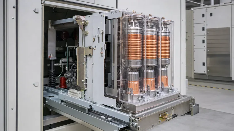
- Withdrawable (Drawout) Execution: The breaker chassis is mounted on a mobile carriage that travels between three distinct physical positions: Service (connected), Test/Disconnected, and Removed. Racking between Service and Test positions must occur with the cubicle door closed to maintain operator safety behind internal arc-resistant boundaries. Automatic metallic safety shutters cover the primary live busbar spouts when the truck is racked out.
- Fixed-Mount Execution: The breaker frame is bolted directly to the switchgear structure, commonly found in compact secondary distribution switchboards, modular containerised power houses, and modern compact ring main units vs metal-clad switchgear lineups. Disconnection requires a separate series-connected three-position disconnector/earthing switch.
Mechanical safety interlocks are critical in vacuum circuit breakers indoor configurations. Standard switchgear engineering must enforce mechanical and electrical prevention logic, including:
- Preventing racking the breaker carriage into or out of the Service position unless the main circuit breaker contacts are confirmed open.
- Preventing closure of the circuit breaker contacts unless the carriage is fully locked in either the Test or Service position.
- Preventing operation of the integral earthing switch if the breaker carriage is in the Service position.
- Preventing closure of the compartment cable access door unless the earthing switch is fully closed (for specific cubicle types), or preventing the breaker from being racked in while the cable compartment door is ajar.
To prevent phase-to-phase and phase-to-earth flashovers caused by atmospheric condensation, indoor VCB cubicles must incorporate thermostatically controlled anticondensation space heaters within both the breaker cassette and the rear cable termination compartments, maintaining internal temperatures 3 °C to 5 °C above the ambient dew point.
Transient Recovery Voltage (TRV) and Current Chopping Phenomena
Transient recovery voltage (TRV) is the voltage that appears across the open contacts of a circuit breaker immediately after current interruption. The rate of rise of recovery voltage (RRRV) dictates whether a vacuum circuit breaker will successfully maintain dielectric isolation or suffer a thermal or dielectric restrike.
Because vacuum possesses high dielectric strength, a vacuum interrupter can force an alternating current to zero ahead of its natural zero-crossing point. This characteristic is known as current chopping. When interrupting small inductive currents—such as those encountered during the switching of unloaded power transformers, shunt reactors, or idle high-voltage induction motors—the arc may destabilise and extinguish at instantaneous values ranging from 2 A to 5 A. The energy trapped in the circuit inductance ($L$) at the instant of chopping transfers into the parallel stray capacitance ($C$), inducing transient overvoltage surges on the connected load side.
The prospective peak overvoltage ($V_{\text{peak}}$) caused by current chopping can be calculated using the circuit energy balance:
$$\frac{1}{2} L I_{\text{chop}}^2 = \frac{1}{2} C V_{\text{surge}}^2 \implies V_{\text{surge}} = I_{\text{chop}} \sqrt{\frac{L}{C}}$$
The total line-to-earth peak voltage experienced by the equipment insulation equals the power-frequency system voltage at the instant of interruption plus the generated surge voltage:
$$V_{\text{peak}} = V_{\text{system\_peak}} + I_{\text{chop}} \sqrt{\frac{L}{C}}$$
Worked Engineering Calculation:
Consider an unloaded 11 kV / 415 V distribution transformer switched by an indoor vacuum circuit breaker. The input parameters are:
- System Phase-to-Earth Peak Voltage ($V_{\text{system\_peak}}$): $\frac{11000}{\sqrt{3}} \times \sqrt{2} = 8,981\text{ V}$
- Transformer Magnetising Inductance ($L$): $45\text{ H}$ (equivalent to a low magnetising current of ~0.78 A RMS)
- Bushing and Cable Stray Capacitance ($C$): $3.5\text{ nF}$ ($3.5 \times 10^{-9}\text{ F}$)
- Vacuum Interrupter Chopping Current ($I_{\text{chop}}$): $3.5\text{ A}$ (typical for CuCr contacts)
Calculate the surge impedance ($Z_0$) of the disconnected transformer circuit:
$$Z_0 = \sqrt{\frac{L}{C}} = \sqrt{\frac{45}{3.5 \times 10^{-9}}} = \sqrt{1.2857 \times 10^{10}} \approx 113,389\ \Omega$$
Calculate the resulting surge voltage component ($V_{\text{surge}}$):
$$V_{\text{surge}} = I_{\text{chop}} \times Z_0 = 3.5\text{ A} \times 113,389\ \Omega = 396,861\text{ V} \approx 396.9\text{ kV}$$
This theoretical value significantly exceeds the 75 kV BIL withstand capability of standard 12 kV switchgear and transformer insulation. In practice, interrupter contact micro-breakdowns (pre-strikes/re-ignitions) and iron losses dampen the peak. However, the calculated surge confirms why engineers must specify protective measures. When switching dry-type transformers, arc furnaces, or rotating machinery, metal-oxide surge arresters (MOVs) or tuned RC snubber circuits (e.g., 0.1 µF to 0.25 µF in series with 20 Ω to 50 Ω) must be installed at the transformer terminals to limit the surge impedance and absorb high-frequency transient reflections.
Operating Mechanisms: Spring-Operated vs Magnetic Actuators
A vacuum circuit breaker requires an external mechanical energy source to overcome contact wipe pressure springs, drive the moving stem through its opening stroke, and accelerate the contacts to speeds between 0.8 m/s and 2.5 m/s. Because vacuum interrupters feature short travel strokes (typically 8 mm to 12 mm at 12 kV, and 16 mm to 22 mm at 36 kV), drive mechanisms can be lighter and more compact than those required for oil or gas breakers.
Two main mechanism types are used across commercial medium-voltage platforms:
- Stored-Energy Spring Mechanisms: The traditional and most common drive configuration utilizes mechanical helical springs. An electric motor, coupled through a reduction gearbox and ratchet gear, charges the closing spring in approximately 5 to 15 seconds. Once released, the closing spring drives the contacts shut and simultaneously charges the opening springs. A mechanical trip latch holds the breaker closed until a trip solenoid receives a protection signal from an external relay, releasing the opening springs. Spring mechanisms are serviceable, rely entirely on mechanical linkages, and permit manual charging with a hand crank during auxiliary power outages.
- Magnetic Actuator (Permanent Magnet) Mechanisms: This modern architecture replaces mechanical latches, motor gearboxes, and trip springs with a bistable magnetic system and an electronic control module. The mechanism contains a moving soft-iron armature held in either the open or closed position by permanent neodymium-iron-boron magnets without continuous electrical power. Switching states requires pulsing an electromagnetic coil located on the drive shaft, powered by high-reliability electrolytic storage capacitors. Magnetic actuators reduce the total component count from several hundred mechanical parts down to fewer than thirty, offering up to 100,000 operations without mechanical adjustment.
For standard distribution duty in accordance with MV switchgear engineering specifications, stored-energy spring drives remain preferred where standard DC auxiliary supply networks (24 V, 48 V, 110 V, or 220 V DC) are maintained and personnel are familiar with mechanical latch maintenance.
Testing, Commissioning, and Contact Wear Inspection
Commissioning and routine preventive maintenance of a vacuum circuit breaker ensure that vacuum integrity, primary contact thickness, and mechanical opening times remain within manufacturer tolerances. Because vacuum interrupter bottles are hermetically sealed, direct visual inspection of internal contacts is not possible, requiring indirect physical measurements and electrical tests.
Field testing procedures follow a standard engineering sequence:
- Contact Erosion / Wear Indicator Check: Interrupter stems feature external etched gauge marks or mechanical vernier callipers mounted to the drive carriage. With the breaker closed, technicians measure the distance between the fixed reference point and the moving contact stem. Contact erosion, caused by cumulative interruption of fault currents, reduces this dimension. If contact material loss exceeds the allowable limit (typically 2.0 mm to 3.0 mm), the vacuum bottle must be replaced.
- Contact Wipe and Stroke Measurement: Contact wipe is the compression distance the external contact springs travel after physical contact touchdown. Stroke is the total distance traversed by the moving contact from fully open to fully closed. Verification is performed using mechanical dial indicators or digital displacement transducers to ensure sufficient contact pressure is maintained to avoid contact overheating under rated current.
- Vacuum Integrity (Dielectric Withstand) Test: The bottle's internal vacuum level is evaluated using an AC high-potential test set. With the breaker open, an overpotential is applied across the contact gap for 60 seconds (e.g., 27 kV RMS for a 12 kV breaker, or 65 kV RMS for a 36 kV breaker per IEC 62271-1). If the vacuum has breached to atmosphere, internal ionization occurs and the bottle breaks down, tripping the test set. DC high-potential testing may also be used, but AC is preferred to avoid X-ray radiation emission hazards during high DC stress.
- Static Contact Resistance Measurement: A calibrated digital low-resistance ohmmeter (DLRO) injecting a minimum of 100 A DC is connected across the primary terminals of each pole. Micro-ohm values must not exceed factory baseline specifications (typically between 15 µΩ and 35 µΩ per pole). High resistance indicates oxidized finger clusters, damaged flexible shunts, or contact degradation.
- Mechanical Timing and Synchronization: A breaker timing analyzer measures the duration from trip coil energization to contact separation (opening time, typically 30 ms to 50 ms) and close coil energization to contact touching (closing time, typically 40 ms to 70 ms). Pole-to-pole non-simultaneity (discrepancy) must remain under 2 ms during opening and 4 ms during closing.
Engineering Specification Checklist for Procurement RFQs
Creating an engineering procurement specification for a vacuum circuit breaker requires clear criteria to prevent vendor ambiguities and avoid costly revisions during project execution. The table below outlines the core parameters that project engineers, consultants, and EPC contractors must define when issuing an equipment Request for Quotation (RFQ).
| Specification Category | Key Parameter to Specify | Engineering Selection Criteria / Standard Options |
|---|---|---|
| System Parameters | Nominal & Max System Voltage | 3.3 kV, 6.6 kV, 11 kV (12 kV max), 22 kV (24 kV max), 33 kV (36/40.5 kV max) |
| Insulation Levels | Power-Frequency / Impulse (BIL) | 12 kV: 28 kV / 75 kV; 24 kV: 50 kV / 125 kV; 36 kV: 70 kV / 170 kV (IEC 60071) |
| Current Ratings | Continuous Load Current (Ir) | 630 A, 1250 A, 2000 A, 2500 A, 3150 A, or 4000 A (forced-cooled) |
| Fault Interrupting | Short-Circuit Breaking (Isc) | 25 kA, 31.5 kA, 40 kA, or 50 kA RMS with 3-second thermal withstand (Ik) |
| Dynamic Making | Peak Withstand Current (Ip) | 2.5 x Isc (50 Hz) or 2.6 x Isc (60 Hz) standard; state high DC time constants if applicable |
| Construction Type | Mounting Format & Partitioning | Withdrawable carriage on guide rails or fixed-mount; LSC2B-PM metal-clad enclosure |
| Operating Duty | Autoreclosing Duty Sequence | O - 0.3s - CO - 15s - CO (standard for overhead grid feeders) or O - 0.3s - CO - 3min - CO |
| Drive Mechanism | Operating Mechanism Type | Spring-charged (motorised with manual backup) or magnetic actuator (permanent magnet) |
| Control Voltages | Motor, Close & Trip Solenoids | DC: 24 V, 48 V, 110 V, 125 V, 220 V; AC: 110 V, 230 V (50/60 Hz) |
| Auxiliary Switches | Auxiliary Contact Quantity | Minimum 6 NO + 6 NC, 8 NO + 8 NC, or 12 NO + 12 NC free contacts for SCADA |
| Environmental Siting | Ambient Temp & Altitude | -5 °C to +40 °C standard; specify derating factors for altitudes exceeding 1000 m |
| Protection Device | Surge Protection Integration | Station-class gapless ZnO surge arresters or RC snubbers for inductive loads |
Specifying these ratings in the tender document ensures proper coordination with upstream protection relays, substation DC batteries, and downstream electrical switchgear systems.
Next steps: specifying and sourcing
When preparing single-line diagrams (SLDs) and technical datasheets for custom distribution projects, clear coordination between the vacuum circuit breaker, primary protection relays, and cubicle enclosures is vital. Forward your system parameters—including continuous rated current, short-circuit clearing duty, control voltages, and protection requirements—to our engineering team. We supply type-tested HV/LV switchgear panels and integrated prefabricated transformer substations tailored to IEC and IEEE standards. Visit our quotation page or complete our inquiry form to receive project-specific schematics, technical schedules, and budget proposals.
Frequently asked questions
What is the typical lifespan of a vacuum circuit breaker?
A modern vacuum circuit breaker has an operational lifespan of 20 to 30 years. Under standard operating conditions, the vacuum interrupter can handle 10,000 to 30,000 mechanical operations and between 30 and 100 full short-circuit interruptions before requiring interrupter replacement.
Why do vacuum circuit breakers require surge arresters for motor loads?
Vacuum circuit breakers can prematurely interrupt small inductive currents before natural current zero, a phenomenon known as current chopping. This rapid current drop generates high-voltage inductive surges (V = Ichop * sqrt(L/C)) that can exceed equipment insulation ratings unless clamped by surge arresters or RC snubbers.
How do you test the vacuum integrity of a VCB bottle?
Vacuum integrity is verified during commissioning using an AC high-potential withstand test across open contacts for 60 seconds. If the vacuum has degraded to atmospheric air, dielectric breakdown occurs at a lower threshold, causing the testing unit to trip on overcurrent.
Can a vacuum circuit breaker be used in DC systems?
Standard vacuum circuit breakers are designed for AC circuits where natural current zero-crossings enable arc quenching. Using vacuum interrupters in high-voltage DC applications requires specialised active or passive LC counter-pulse circuits to force the DC current to zero artificially.
What is the difference between fixed and withdrawable vacuum circuit breakers?
A fixed vacuum circuit breaker is bolted permanently to the switchgear structure and requires separate disconnectors for isolation, whereas a withdrawable breaker is mounted on a rolling carriage that racks out from the live busbars, incorporating safety shutters for safe maintenance.
What contact material is used inside modern vacuum circuit breakers?
Modern vacuum circuit breakers use copper-chromium (CuCr) alloys, typically 75% copper and 25% chromium. This composite metallurgy balances high thermal conductivity and low resistance with erosion resistance and minimal current chopping.
Tags: vacuum circuit breaker vacuum circuit breakers indoor switchgear medium voltage substations


