Key takeaways
- A substation control house protects secondary systems including microprocessor protection relays, SCADA remote terminal units, station DC batteries, and MV switchgear from environmental extremes.
- Modular integrated substation control enclosures cut civil construction schedules by 40% to 60% compared to conventional in-situ masonry buildings.
- HVAC systems for prefabricated substations require N+1 redundancy sized to handle total internal equipment sensible heat dissipation alongside peak envelope solar gains.
- Clearances inside any modular substation building must strictly satisfy NFPA 70 Article 110.26 working space mandates and IEEE 484 hydrogen ventilation requirements.
- Comprehensive Factory Acceptance Testing (FAT) allows 100% pre-commissioning of relay racks, DC auxiliary circuits, and station automation before site delivery.
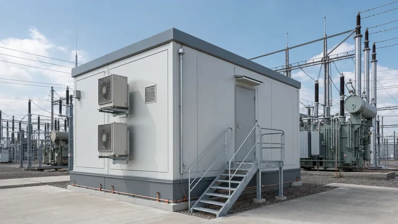
Quick answer: A substation control house is a purpose-engineered, climate-controlled prefabricated or masonry enclosure that shelters critical electrical protection, automation, communication, and DC auxiliary power systems in high-voltage and medium-voltage substations. It isolates sensitive secondary equipment from outdoor weather, electromagnetic interference, and seismic stress, ensuring uninterrupted grid control and monitoring.
In utility, industrial, and renewable power infrastructure, the electrical switchyard relies entirely on secondary systems to detect abnormal line conditions, isolate faults, and transmit operational telemetry. Whether configured as a masonry structure or a factory-tested modular substation building, this facility houses the intelligence of the electrical network. As utilities transition toward rapid grid modernisation, specifying a factory-built prefabricated substation enclosure has superseded traditional cast-in-place concrete construction for substations up to 500 kV.
Selecting and engineering these structures requires balancing structural resilience, electrical clearances, thermal dissipation calculations, and arc-flash personnel mitigation. This guide provides project engineers, consultants, and procurement managers with practical sizing methodologies, layout best practices, and integration standards for modular integrated substation control enclosures.
Core Functions of a Substation Control House
The primary function of a substation control house is to provide an environmentally stable, secure, and electrically shielded space for secondary protection and control apparatus. Without this centralised envelope, sensitive microprocessor-based intelligent electronic devices (IEDs) would fail rapidly due to outdoor ambient temperature swings, condensation, airborne particulates, and electromagnetic fields generated by high-voltage busbars.
Within the substation topology, the control enclosure consolidates several mission-critical operational systems:
- Protective Relay Panels: Microprocessor relays executing line differential, distance, busbar, and transformer protection, as detailed in our guide to transformer protection systems.
- SCADA and Automation Racks: Remote Terminal Units (RTUs), human-machine interfaces (HMIs), sequence-of-events recorders, and ethernet switches conforming to IEC 61850 or DNP3 network architectures.
- Station DC Auxiliary Power: Vented lead-acid (VLA) or valve-regulated lead-acid (VRLA) battery banks, battery chargers, and DC distribution boards that supply trip-coil power during AC blackout scenarios.
- AC Auxiliary Distribution: Station service panels, automatic transfer switches (ATS), and uninterruptible power supply (UPS) systems delivering 400/230 V or 480/208 V auxiliary power.
- Medium-Voltage (MV) Switchgear: In many facilities, indoor metal-clad or gas-insulated switchgear lineups are co-located within the building envelope to prevent outdoor weathering, an arrangement explored in our MV switchgear engineering guide.
- Telecommunications & Metering: Optical fibre patch frames, power-line carrier equipment, microwave transceivers, and revenue-grade tariff meters.
Prefabricated Substation vs Brick-and-Mortar Buildings
A prefabricated electrical substation building offers dramatic reductions in project lead times and civil labour risks compared to traditional site-built masonry structures. While civil contractors constructing masonry buildings face weather delays, multi-trade coordination issues, and variable workmanship, a factory-assembled prefab substation enclosure is fabricated concurrently with outdoor yard civil works.
The following engineering decision matrix compares the two structural approaches across standard project parameters:
| Evaluation Criterion | Prefabricated Modular Enclosure | Conventional Masonry / Cast Concrete |
|---|---|---|
| Fabrication & Delivery Time | 12 to 18 weeks (concurrent with site civil works) | 28 to 40 weeks (sequential on-site construction) |
| On-Site Labour Requirement | Minimal (rigging, setting, external cabling) | Extensive (bricklayers, plasterers, roofers, painters) |
| Pre-Commissioning Level | 90% to 100% factory pre-wired and tested (FAT) | 0% (all panels mounted and wired on-site) |
| Structural Weight | Lightweight structural steel base (150 - 250 kg/m²) | Heavy reinforced concrete / blockwork (>600 kg/m²) |
| Foundation Cost | Low (engineered concrete piers or strip footings) | High (deep continuous slab or grade beam network) |
| Seismic & Wind Resistance | IBC / ASCE 7 engineered steel frame (up to 250 km/h wind) | Subject to on-site mortar quality and reinforcing control |
| Future Relocation / Expansion | High (modular split lines enable physical expansion) | Zero (demolition required for layout alterations) |
| Quality Assurance | Factory controlled under ISO 9001 and AWS D1.1 welding | Field QA subject to site supervision and ambient weather |
For fast-track transmission connections, renewable energy collector systems, and industrial plants, specifying a modular substation drastically lowers capital risk by compressing the critical path schedule.
Structural Architecture of Modular Substation Buildings
A durable modular substation building is engineered around a structural steel base skid designed to support static equipment loads and dynamic deflection stresses during crane hoisting and transport. The structural base typically utilises ASTM A36 or ASTM A992 structural channels and wide-flange I-beams, welded in compliance with AWS D1.1 standards, with cross-members spaced at 300 mm to 400 mm centres beneath heavy switchgear and battery bays.
The building envelope incorporates several distinct structural layers:
- Floor System: Fabricated from 6 mm to 8 mm diamond plate or smooth steel plate stitch-welded to the undercarriage, insulated beneath with polyurethane foam or mineral wool, and finished internally with a 3 mm high-dielectric, chemical-resistant static-dissipative vinyl tile or epoxy coating meeting ASTM F150.
- Wall Construction: Interlocking structural panels constructed from galvanised steel (G90) or Galvalume (AZ150) sheet, ranging from 1.5 mm to 2.0 mm (14 to 16 gauge) exterior thickness. For harsh corrosive or coastal environments, 304 or 316 stainless steel exterior cladding is specified.
- Insulation and Thermal Performance: Non-combustible mineral wool (meeting ASTM E136) or polyisocyanurate closed-cell foam cores provide thermal insulation values between R-15 and R-30 (U-values from 0.38 down to 0.19 W/m²·K), preventing condensation and minimizing HVAC operating draw.
- Roof Assembly: Self-framing or standing-seam roofs sloped at a minimum pitch of 1:50 to facilitate positive rainwater shedding. Industrial gutters, downspouts, and a minimum roof live load rating of 1.5 to 2.5 kPa ensure survivability under heavy snow accumulations.
- Fire Resistance: Enclosures installed in proximity to outdoor oil-filled equipment must comply with NFPA 850 recommendations, typically requiring a 2-hour fire resistance rating tested in accordance with UL 263 or ASTM E119.
Electrical Clearance and Equipment Layout Standards
Equipment layout within a substation control house must comply with national safety codes to maintain safe working clearances and rapid egress during arc-fault emergencies. In North American jurisdictions, NFPA 70 (National Electrical Code, NEC) Article 110.26 dictates minimum working clearances based on nominal line-to-ground voltage levels.
For low-voltage protection panels and 120/208/480 V auxiliary boards (Condition 1: exposed live parts on one side and no live or grounded parts on the other), a minimum clear distance of 914 mm (3.0 ft) is mandatory. Where live parts face grounded enclosures across an aisle (Condition 2), this clearance increases to 1,067 mm (3.5 ft). When configuring medium-voltage metal-clad switchgear operating up to 15 kV, clearances under NEC Table 110.34(A) must expand to 1,524 mm (5.0 ft) for Condition 2 layouts. Rear-access switchgear aisles require an additional 760 mm to 914 mm clear corridor behind the enclosures.
Personnel safety further dictates that rooms containing equipment rated 1,200 A or more and wider than 1.8 m (6.0 ft) must have double-exit outward-swinging doors equipped with panic hardware (NFPA 70 Article 110.26(C)(2)). Integrating internal arc mitigation equipment and following safe operational practices is essential, as covered in our analysis of arc flash safety in electrical installations.
Cabling infrastructure typically relies on an elevated overhead wireway network or a sub-floor cable trench system. Heavy medium-voltage feeder cables entering the building are routed through floor cutouts sealed with transit frames certified to UL 1479 to maintain building fire separation and prevent rodent ingress.
HVAC, Environmental and Battery Sizing: A Worked Calculation
Environmental control in a substation control house must maintain ambient indoor temperatures between 18 °C and 25 °C with relative humidity controlled under 60% non-condensing to safeguard solid-state electronic relays. Sizing the dual HVAC systems requires tallying total sensible heat dissipation from energized internal gear and calculating the envelope thermal conduction load under extreme outdoor ambient temperatures.
Consider an actual engineering scenario for an isolated modular integrated substation control enclosures unit measuring 12.0 m (L) × 3.6 m (W) × 3.2 m (H), situated in an industrial yard with an outdoor peak summer ambient temperature of 45 °C and an interior design setpoint of 22 °C ($\Delta T = 23\text{ °C}$ or $41.4\text{ °F}$).
Step 1: Calculate Internal Heat Dissipation ($Q_{\text{int}}$)
- 10 × Microprocessor Protection & Automation Panels: $10 \times 250\text{ W} = 2,500\text{ W}$
- 2 × 125 VDC, 100 A High-Frequency Battery Chargers (operating at 90% efficiency, heat loss $\approx 10\%$): $2 \times (125\text{ V} \times 100\text{ A} \times 0.10) = 2,500\text{ W}$
- Station Auxiliary LV AC Panelboards: $1,200\text{ W}$
- Internal LED Lighting & Transducers: $800\text{ W}$
- Total internal sensible load: $Q_{\text{int}} = 2,500 + 2,500 + 1,200 + 800 = 7,000\text{ W}$ ($23,885\text{ BTU/hr}$)
Step 2: Calculate Envelope Transmission Load ($Q_{\text{env}}$)
- Total Gross Wall Area: $2 \times (12.0 + 3.6) \times 3.2 = 99.84\text{ m}^2$ ($1,075\text{ sq ft}$)
- Roof Surface Area: $12.0 \times 3.6 = 43.2\text{ m}^2$ ($465\text{ sq ft}$)
- Total External Exposed Area ($A$): $1,540\text{ sq ft}$
- Envelope Wall & Roof Overall Thermal Transmittance ($U$-value for an R-20 assembly): $U = 1 / 20 = 0.05\text{ BTU}/(\text{hr}\cdot\text{sq ft}\cdot\text{°F})$
- Base Envelope Heat Gain: $Q = U \times A \times \Delta T = 0.05 \times 1,540 \times 41.4 = 3,188\text{ BTU/hr}$
- Solar Radiation Solar Heat Gain Factor (adding roof solar peaking allowance of 1,800 BTU/hr): $Q_{\text{env}} = 3,188 + 1,800 = 4,988\text{ BTU/hr}$ ($1,462\text{ W}$)
Step 3: Total Sensible Cooling Capacity and Unit Selection
Total continuous sensible load = $Q_{\text{int}} + Q_{\text{env}} = 23,885 + 4,988 = 28,873\text{ BTU/hr}$ ($8.46\text{ kW}$). Applying a standard 20% engineering margin yields a design cooling load of $34,648\text{ BTU/hr}$ (equivalent to 2.89 Tons of Refrigeration [TR]).
Engineers specify dual wall-mounted exterior HVAC packages rated at 3.5 TR (12.3 kW / 42,000 BTU/hr) each. Operating on an automated lead-lag controller with cycle alternation, either unit handles 100% of the maximum thermal load if the other unit trips, fulfilling N+1 utility redundancy mandates.
Step 4: Battery Room Ventilation Rates
Station lead-acid battery banks produce hydrogen ($H_2$) gas during charging cycles. In accordance with IEEE 484 and NFPA 1 (Chapter 52), the continuous mechanical ventilation system must limit $H_2$ concentration to less than 1.0% by volume. Airflow ($Q_v$) is sized using the standard hydrogen release equation:
$$Q_v = \frac{N \times I \times 0.0156\text{ ft}^3/\text{hr}}{0.01} \times \frac{1}{60\text{ min/hr}}$$
Where $N$ is the number of series cells (60 cells for a nominal 125 V bank) and $I$ is the maximum equalising charging current (e.g., 20 A). Spark-proof exhaust fans interlocked with hydrogen detectors provide fail-safe air exhaust to the outdoor yard.
DC Power Systems and Relay Protection Integration
A substation control house contains the electrical network's primary line of defence during faults, meaning its auxiliary DC power infrastructure cannot be compromised by utility blackouts. A 125 VDC or 250 VDC battery bank operates permanently connected in parallel across filtered industrial battery chargers. Under normal circumstances, the chargers convert AC station service power into regulated DC float voltage, powering relay racks while floating the cells.
Upon loss of external station service AC, the battery bank seamlessly assumes the full station load without any switching interruption. It must provide continuous tripping and closing currents for all outdoor transmission breakers, power relay coils, energize SCADA radios, and sustain emergency DC ingress lighting for a minimum reserve time of 8 to 12 hours (per IEEE 485 sizing standards).
Secondary cabling between outdoor switchyard current transformers (CTs), potential transformers (PTs), and indoor relays enters the control house via subterranean cable trenches. CT secondary circuits terminate on shorting terminal blocks to permit testing without open-circuiting the secondary loops, which would generate lethal peak voltages. Shielded twisted-pair wiring and direct fibre-optic links from outdoor optical transformers are grounded at a single star-point to avoid ground potential rise (GPR) loop currents during severe ground-fault conditions on adjacent substation transformers.
Testing and Commissioning Prefabricated Substations
A critical commercial and technical benefit of sourcing a prefabricated substation is the ability to complete Factory Acceptance Testing (FAT) before the building is dispatched to the field. Commissioning engineers carry out rigorous procedures inside the controlled factory environment to eliminate field wiring modifications.
The standard multi-stage testing procedure follows an established quality sequence:
- Structural Integrity and Weld Inspection: Non-destructive testing (NDT), magnetic particle, or ultrasonic examination of primary skid welds in accordance with AWS D1.1, followed by paint thickness verification (minimum 120-150 microns dry film thickness).
- Air and Rain Penetration Testing: Exterior walls, doors, and penetration gland plates undergo water-spray leakage testing (ASTM E1105 or static water-head testing) to verify gasket water-tightness under simulated gale conditions.
- Dielectric and Insulation Testing: Point-to-point insulation resistance testing (megohmmeter testing at 1,000 VDC) across all factory-installed AC auxiliary wiring, DC distribution boards, and lighting circuits.
- Relay Secondary Injection and Protection Logic: Microprocessor relays are energized and injected with three-phase secondary currents and voltages to verify breaker tripping matrices, reclosing sequences, and interlocks before transport.
- SCADA Telemetry and Communication Verification: Every digital input, analog transducer measurement, and control point is polled via DNP3 or IEC 61850 protocol to verify telemetry transmission back to the master station interface.
- HVAC Performance and Automated Transfer Switch Testing: Verification of automatic AC source transfer between normal and emergency feeds, followed by HVAC lead-lag cycling and alarm initiation under simulated thermostatic faults.
Procurement and Engineering Checklist for RFQs
When preparing a Request for Quotation (RFQ) for a modular substation enclosure, procurement engineers must provide detailed site-specific environmental ratings and electrical interfaces. Incomplete specifications often lead to post-award design revisions that delay fabrication schedules.
The following technical checklist should be integrated into the mechanical and civil scope of work for the equipment manufacturer:
| Specification Parameter | Standard Design Requirements | Project Specific Value |
|---|---|---|
| Applicable Building Codes | IBC 2021 / ASCE 7-16 / NFPA 70 / NFPA 850 | Specify local jurisdiction code |
| Wind Load Rating | Basic wind speed: 180 to 240 km/h (Risk Category III/IV) | Site wind exposure category (C or D) |
| Seismic Acceleration | Seismic Design Category D, E, or F ($S_s \ge 1.5g$) | Site-specific spectral acceleration ($S_s, S_1$) |
| Thermal Insulation (Skid/Wall/Roof) | R-19 floor / R-20 walls / R-30 roof (mineral wool core) | Target U-values per thermal zone |
| Fire Resistance Period | Exterior: 2-hour rating (UL 263 / ASTM E119) | Specify distance to power transformers |
| Floor Loading Rating | Uniform load: 12.0 kPa; Point load: 15.0 kN under gear | Match largest switchgear section weight |
| External Wall Material | 2.0 mm galvanised steel with heavy-duty marine epoxy coat | Galvanised, Galvalume, or 316 Stainless |
| HVAC Redundancy Architecture | Dual 100% capacity N+1 wall-hung units with lead-lag | Ambient design dry bulb (-30 °C to +50 °C) |
| DC Battery Separation | Dedicated vapor-tight room with spark-proof exhaust | Specify cell chemistry (VLA vs VRLA vs LFP) |
| Cable Entry Provisions | Removable 4 mm aluminium gland plates with firestop | Overhead tray vs raised computer floor |
Next steps: specifying and sourcing
Selecting the right structural layout and thermal profile for a substation control house determines the long-term reliability and personnel safety of your switchyard installation. Sourcing engineers should compile single-line diagrams, physical switchyard plot plans, environmental ambient data, and switchgear dimensions prior to bidding.
To configure integrated electrical packages, explore our dedicated equipment lines including the prefabricated transformer substation and complete HV and LV switchgear assemblies. When your project team is ready to finalise structural loadings, HVAC calculations, and factory pre-commissioning schedules, submit your project specifications through our substation quotation portal or contact our application engineers via the engineering consultation page.
Frequently asked questions
What is the primary purpose of a substation control house?
A substation control house protects critical electrical monitoring, automation, and protection systems from adverse environmental conditions. It houses microprocessor protective relays, SCADA panels, station DC battery systems, and medium-voltage switchgear in a climate-controlled, secure enclosure.
How does a prefabricated substation building save project costs?
A prefabricated substation building cuts project costs by shifting construction from the field to a factory environment, shortening schedules by 40% to 60%. It enables concurrent switchyard civil works while internal equipment, wiring, and automation racks are pre-installed and tested before dispatch.
What clearances are required inside a modular substation building?
Clearances inside a modular substation building are governed by NFPA 70 Article 110.26, requiring at least 914 mm to 1,067 mm of clear working space in front of low-voltage panels. Medium-voltage switchgear operating up to 15 kV requires minimum clearances of 1,524 mm.
Why is N+1 HVAC redundancy necessary in substation control houses?
N+1 HVAC redundancy guarantees that if one cooling unit suffers a mechanical breakdown, the backup unit maintains design temperatures without disruption. This prevents microprocessor relays and battery chargers from overheating, avoiding premature component degradation or thermal tripping.
How are batteries ventilated in a prefabricated control house?
Batteries in a prefabricated control house are installed in a segregated room or enclosure ventilated by continuous spark-proof exhaust fans per IEEE 484 and NFPA 1. This mechanical ventilation prevents combustible hydrogen gas concentrations from exceeding 1.0% by volume during charging cycles.
Tags: substation control house prefabricated substation modular substation building modular substation prefabricated electrical substation modular integrated substation control enclosures


