Key takeaways
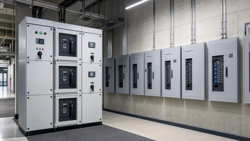
- Switchboards are floor-mounted, freestanding enclosures rated up to 6,000 A with front or rear access, while panelboards are wall-mounted or flush-mounted enclosures typically rated up to 1,200 A with front access only.
- Under North American standards, switchboards are governed by UL 891 and NEMA PB 2, whereas panelboards are certified to UL 67 and NEMA PB 1.
- International installations classify both equipment types under IEC 61439-1 and IEC 61439-2, distinguishing them by their rated current (InA) and internal separation forms ranging from Form 1 up to Form 4b.
- Switchboards house larger overcurrent devices, integrated switchgear control panel instrumentation, and compartments for drawout breakers, making them suitable as primary service entrance equipment.
- Panelboards act as secondary or tertiary branch distribution units, distributing electrical feeds directly to lighting, appliances, and localized motor loads.
Quick answer: In a switchboard vs panelboard evaluation, the core distinction lies in mounting, current capacity, and structural layout: a switchboard is a freestanding, floor-mounted assembly rated up to 6,000 A for primary power routing, whereas a panelboard is a wall-mounted enclosure rated up to 1,200 A for downstream branch circuit distribution.
Low-voltage power distribution networks rely on a clear physical and electrical hierarchy to deliver power safely from utility feeds or power transformers down to final branch circuits. Designing an industrial facility or commercial infrastructure project requires selecting the correct assembly tier. Misclassifying an assembly risks code violations under National Electrical Code (NEC) Article 408 or IEC 61439-2, improper short-circuit withstand capabilities, and costly spatial re-engineering in electrical rooms. Understanding the mechanical, electrical, and operational differences between an lv panel board and a main distribution switchboard ensures compliance and operational safety.
What Is the Difference Between Switchboard and Panelboard?
The fundamental difference between switchboard and panelboard equipment stems from how building codes define their physical construction, internal access, and service location. According to NEC Article 100 and Article 408, a panelboard is a single panel or group of panel units designed for assembly in the form of a single panel, including buses and automatic overcurrent devices, equipped with or without switches for the control of light, heat, or power circuits. It is placed in a cabinet or cutout box, mounted in or against a wall, partition, or other support, and accessible only from the front.
Conversely, the NEC defines a switchboard as a large single panel, frame, or assembly of panels on which are mounted, on the face, back, or both, switches, overcurrent and other protective devices, buses, and usually instruments. Switchboards are freestanding, accessible from the front, rear, or both, and are not intended to be installed within cabinet enclosures. In typical low-voltage networks designed around an electrical switchgear system, the switchboard accepts the main incoming secondary feed from an upstream power transformer, while downstream panelboards feed the terminal equipment.
Switchboard vs Panelboard: Technical Comparison
When specifying equipment, engineers must evaluate electrical parameters including continuous ampacity, short-circuit withstand ratings, access requirements, and international compliance standards. The table below outlines the primary engineering differences governing these assemblies.
| Engineering Parameter | Panelboard (UL 67 / NEMA PB 1) | Switchboard (UL 891 / NEMA PB 2) | LV Switchgear (UL 1558 / IEC 61439-2) |
|---|---|---|---|
| Maximum Current Rating | Up to 1,200 A (typical max 800 A) | Up to 6,000 A | Up to 10,000 A |
| Voltage Rating (AC) | Up to 600 V AC | Up to 600 V AC / 1,000 V AC | Up to 1,000 V AC |
| Mounting Configuration | Wall-mounted, flush, or surface | Floor-mounted, freestanding | Floor-mounted, freestanding |
| Access Requirements | Front access only | Front only or front and rear | Front and rear compartmentalised |
| Short-Circuit Current Rating (SCCR) | 10 kA to 100 kA RMS symmetrical | 25 kA to 200 kA RMS symmetrical | Up to 150 kA / 200 kA (30-cycle withstand) |
| Internal Segregation Form | Form 1 to Form 2b (IEC) | Form 1 to Form 4b (IEC) | Form 4b standard (isolated compartments) |
| Overcurrent Device Types | Moulded Case Circuit Breakers (MCCB), MCB | Fixed or plug-in MCCB, Insulated Case (ICCB) | Drawout Air Circuit Breakers (ACB) |
| Primary Application | Lighting, receptacles, branch motors | Main distribution, motor control feeding | Critical infrastructure, continuous industrial process |
While an lv switchgear assembly provides 30-cycle short-time withstand capabilities without instantaneous trips, switchboards typically rely on instantaneous trip elements to clear high fault levels unless specifically engineered for selective coordination under UL 891. For broader structural differences between heavy switchgear and switchboards, review our detailed guide on switchgear vs switchboard design principles.
Busbar Architecture and Switchgear Components Inside LV Distribution Assemblies
The internal arrangement of busbars and protective elements determines how an assembly behaves under continuous thermal load and dynamic electromagnetic stress during a fault. In an lv switchgear or switchboard enclosure, busbars are constructed of high-conductivity electrolytic copper (Cu-ETP, minimum 99.9% purity) or electrical-grade aluminium (6101-T6 alloy). Switchboards feature busbar ratings designed for cross-sectional current densities following standards such as UL 891 Table 26, which prescribes maximum temperature rises of 65 degrees Celsius over a 40 degrees Celsius ambient.
Dynamic forces during a bolted short circuit generate peak forces proportional to the square of the peak fault current:
F = (k × Ipeak2) / d
In this equation, k represents the physical geometry factor, Ipeak is the crest value of the fault current, and d is the centre-to-centre distance between phases. Switchboard busbar supports must use high-strength glass-reinforced polyester or cycloaliphatic insulators braced to withstand mechanical stresses exceeding 100 kA peak. In contrast, an lv panel board relies on standardized factory-moulded backpans with fixed branch bus tabs, rated for smaller mechanical displacement stresses.
Key switchgear components integrated within a modern switchgear panel include:
- Air Circuit Breakers (ACB) or Insulated Case Breakers: Main and tie disconnects with electronic trip units (LSIG protection curves).
- Instrument Transformers: Current transformers (CTs) conforming to IEC 61869-2 with accuracy classes of 0.2S or 0.5 for revenue metering, and 5P10 or 5P20 for relay protection.
- Switchgear Control Panel: Front-door instrumentation housing digital multi-function meters, power quality analysers, automatic transfer switch (ATS) controllers, and pilot lights.
- Surge Protective Devices (SPD): Type 1 or Type 2 surge suppression devices adhering to UL 1449 or IEC 61643-11 to protect sensitive solid-state components.
Worked Engineering Example: Sizing and Specifying an LV Panel Board vs Main Switchboard
To select between an lv panel board and a distribution switchboard, an engineer must calculate both continuous operational current and prospective short-circuit fault levels. Consider an industrial installation fed by a 1,500 kVA distribution transformer stepping down utility voltage to 415 V, 3-phase, 50 Hz, with a transformer impedance (Z%) of 5.75%.
- Calculate Full-Load Current (FLC):
In = S / (√3 × VLL)
In = 1,500,000 VA / (1.732 × 415 V) = 2,087 A - Calculate Prospective Symmetrical Short-Circuit Current (Isc):
Assuming an infinite primary utility bus for conservative calculation:
Isc = In / (Z% / 100)
Isc = 2,087 A / 0.0575 = 36,295 A (36.3 kA RMS) - Determine Dynamic Asymmetrical Peak Current (Ipk):
Using an IEC 61439-1 peak factor n = 2.1 for power factors below 0.15:
Ipk = 36.3 kA × 2.1 = 76.23 kA peak - Equipment Selection and Evaluation:
The continuous full-load current of 2,087 A exceeds the maximum 1,200 A threshold of standard panelboards. Therefore, the main service entrance requires an lv switchgear or switchboard rated at 2,500 A continuous ampacity with horizontal and vertical busbars braced for at least 50 kA RMS symmetrical (105 kA peak). - Downstream Sub-Distribution:
A downstream feeder breaker in the switchboard (e.g., 400 A frame) routes power through cabling to a production line. The downstream line uses an lv panel board rated at 400 A with a busbar short-circuit rating of 25 kA, relying on cable impedance attenuation or series-rated MCCB protection to satisfy fault interruption duties.
For projects requiring custom power transformer integration to match these fault levels, review our reference on transformer sizing and distribution methods.
Forms of Separation and Standards: UL 891 vs IEC 61439
A critical specification factor separating a heavy switchboard from a light-duty panelboard is the internal form of separation defined in IEC 61439-2. While North American standards (UL 891 and UL 67) focus on dead-front enclosure barriers and wire bending space, IEC standards use internal partitions to safeguard personnel from accidental contact with live adjacent parts during maintenance.
The forms of internal separation include:
- Form 1: No internal separation between busbars, functional units, or terminals. Common in standard branch panelboards.
- Form 2b: Separation of busbars from functional units, with terminals separated from the busbars. Typical in light distribution switchboards.
- Form 3b: Separation of busbars from functional units, and separation of all functional units from each other, but outgoing terminals share a common compartment.
- Form 4b: Separation of busbars from functional units, separation of all functional units from each other, and complete separation of outgoing terminals for each functional unit from all other units. Used in critical industrial switchboards where maintenance occurs on live assemblies.
For high-reliability sites such as chemical processing plants and substations, adopting Form 4b within a switchboard architecture prevents dropped tools or insulation failures from cascading into complete busbar flashovers. Comprehensive guidance on assembly segregation and type testing is detailed in our IEC 61439 low-voltage switchgear guide.
Installation, Clearances, and Maintenance Pitfalls
Inadequate working space and failure to account for thermal dissipation represent the two most common installation mistakes in low-voltage distribution planning. NEC Article 110.26 dictates minimum working clearances for electrical equipment operating at 600 V nominal or less. For systems operating between 151 V and 600 V to ground, the depth of clear working space in front of equipment ranges from 0.9 m (3 ft) to 1.2 m (4 ft), depending on whether exposed live parts face grounded surfaces or opposite live parts.
Practical field pitfalls to prevent include:
- Rear Access Encroachment: Specifying a rear-access switchboard without maintaining the required rear clearance (minimum 0.9 m under NEC 110.26). If space is constrained against a structural wall, a front-access-only switchboard or an array of panelboards must be specified.
- Ignoring Thermal Derating Factors: Enclosing high-amperage breakers in unventilated NEMA 3R or IP54 enclosures without applying temperature derating curves. Breakers operating at 50 degrees Celsius ambient within enclosed assemblies typically experience a 10% to 15% reduction in continuous thermal-magnetic trip capacity unless calibrated for elevated temperatures.
- Violating Wire Bending Radii: Failing to verify gutter space in compliance with NEC Table 312.6(A) and 312.6(B). Routing large parallel 500 kcmil or 240 mm² conductors into a compact lv panel board often violates minimum bending radii, leading to mechanical stress on terminal lugs and thermal hotspots.
Next steps: specifying and sourcing
Selecting between an industrial switchboard and a branch panelboard requires comprehensive load lists, prospective fault current calculations, and space layout analysis. To obtain an accurate quotation for your project, supply our engineering team with your electrical single-line diagrams (SLD), preferred busbar material, enclosure IP/NEMA ingress protection ratings, and required forms of internal separation. Explore our certified HV and LV switchgear assemblies and prefabricated compact transformer substations. You can submit your project single-line diagram directly through our online quotation page or speak with our application engineers on our contact page to configure the optimal distribution solution.
Frequently asked questions
What is the main difference between a switchboard and a panelboard?
A switchboard is a floor-mounted, freestanding enclosure rated up to 6,000 A that provides primary power distribution and can feature front and rear access. A panelboard is a wall-mounted or flush-mounted cabinet rated up to 1,200 A that provides front-accessible branch circuit distribution.
Can a panelboard be used as service entrance equipment?
Yes, a panelboard can serve as service entrance equipment if it is listed as suitable for service equipment (SUSE) under UL 67 and NEC 408.3. It must feature an integrated main breaker or disconnect and provisions for bonding the neutral bus to the ground electrode conductor.
When should you select a switchboard instead of a panelboard?
Select a switchboard when your total calculated service load exceeds 800 A to 1,200 A, when prospective short-circuit levels exceed 65 kA to 100 kA, or when your system requires advanced power metering, surge suppression, and rear cable entry inside a freestanding enclosure.
What are the primary standards governing switchboards and panelboards?
In North America, switchboards are governed by UL 891 and NEMA PB 2, while panelboards follow UL 67 and NEMA PB 1. In international markets, both systems are tested and certified under IEC 61439-1 and IEC 61439-2 low-voltage switchgear and controlgear assembly rules.
What is the difference between switchgear and a switchboard?
Low-voltage switchgear is built to UL 1558 or IEC 61439-2 featuring compartmentalised, drawout air circuit breakers with a short-time withstand rating of up to 30 cycles without instantaneous trips. Switchboards are built to UL 891, generally use fixed or plug-in moulded case breakers, and rely on instantaneous trips to survive short-circuit faults.
Tags: lv switchgear switchgear components switchboard vs panelboard switchgear panel lv panel board


