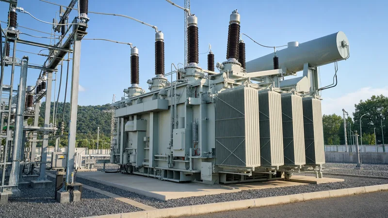
Key takeaways
- An electrical transformer transfers alternating current energy between circuits via mutual magnetic induction without changing operational frequency.
- Stepping up transmission voltage reduces conductor current proportionally, cutting line thermal losses by the square of the current reduction factor.
- Transformer efficiency typically exceeds 98.5% to 99.5%, with losses categorized into core no-load losses and winding load losses per IEC 60076-1.
- Transformer impedance percentage determines short-circuit current withstand capabilities and parallel operation suitability.
- Routine diagnostic testing, including turns ratio, insulation resistance, and winding resistance, confirms dielectric and mechanical integrity prior to energisation.
Quick answer: An electrical transformer is a static electromagnetic device that transfers alternating current electrical energy between circuits at matched frequency while altering voltage and current levels. By stepping up voltage for transmission and stepping it down for local consumption, transformers minimise resistive grid losses and ensure safe end-use utilisation.
In electrical engineering, transformers and power delivery systems are inextricably linked. Whether handling bulk generation at 22 kV, bulk transmission at 400 kV, or industrial sub-distribution at 400 V, the electrical transformer serves as the central node of modern utility grids. Understanding transformer basics, operational theory, internal construction, and thermal dynamics is essential for specifying assets that deliver dependable performance over a standard 30-to-40-year design lifecycle.
How Do Transformers Work? Operational Principles and Physics
To define the transformer in physical terms: it is a stationary electromagnetic machine that converts alternating voltage and current through mutual induction between two or more stationary windings. The fundamental transformer working principle relies on two core physical laws: Faraday's law of electromagnetic induction and Lenz's law. In modern transformers electrical engineering, these laws govern how electrical energy converts into a magnetic field within an insulated core and reconstitutes as electrical energy in a secondary winding.
When an alternating voltage $V_1$ excites the primary winding, it drives an alternating magnetising current through the coil. This current establishes a time-varying magnetic flux $\Phi$ within the laminated silicon steel core. The continuous flux path links the secondary winding turns, inducing an electromotive force (EMF) described by Faraday's equation:
$$e = -N \frac{d\Phi}{dt}$$
Where $N$ denotes the number of turns. According to Lenz's law, the polarity of this induced EMF opposes the flux change producing it. In a transformer with an open secondary circuit, negligible power is drawn beyond that required to overcome core hysteresis and eddy current losses. When a load connects to the secondary terminal, load current flows, establishing a counter-magnetomotive force. The primary winding draws additional current from the grid to maintain balance, preserving core flux equilibrium. Thus, transformers operate on the principle of mutual flux linkage across an insulated transformer electrical circuit, requiring no mechanical movement or direct galvanic connection between primary and secondary circuits.
What Is the Function of the Transformer in Power Systems?
The core function of the transformer is to adjust alternating voltage levels throughout the power grid to maximise transmission efficiency, regulate distribution networks, and provide electrical isolation between differing voltage tiers. Without voltage transformation, bulk transmission of electrical power over regional distances would be physically and economically unfeasible due to excessive conductor resistance losses.
Transmission line power loss is governed by Joule's law, expressed as $P_{\text{loss}} = 3 I^2 R$ for a balanced three-phase system, where $I$ represents phase current and $R$ represents conductor line resistance. Because apparent power is defined as $S = \sqrt{3} V I$, elevating transmission voltage $V$ reduces current $I$ proportionally for an identical power throughput. Because losses scale with the square of the current, doubling system voltage cuts line losses by 75%.
Consider a practical comparison for transmitting 10 MVA of active electrical power over a 20 km sub-transmission feeder using an ACSR conductor with a total route loop resistance of $8\ \Omega$:
- Scenario A (Unstepped 11 kV transmission): Line current is calculated as $I = 10,000\text{ kVA} / (\sqrt{3} \times 11\text{ kV}) = 524.86\text{ A}$. The total line loss equals $3 \times (524.86\text{ A})^2 \times 8\ \Omega = 6.61\text{ MW}$. This equates to a catastrophic 66.1% energy loss across 20 km.
- Scenario B (Stepped-up 132 kV transmission): Line current is calculated as $I = 10,000\text{ kVA} / (\sqrt{3} \times 132\text{ kV}) = 43.74\text{ A}$. The total line loss equals $3 \times (43.74\text{ A})^2 \times 8\ \Omega = 45.91\text{ kW}$. The resulting line loss is only 0.46% of transmitted capacity.
By shifting voltage from generation thresholds to high-voltage grid levels, transformer energy management makes long-distance transmission viable before stepped-down delivery to industrial loads or municipal distribution networks.
Transformer and Its Types: Primary Classifications
Transformers are categorised by cooling medium, construction architecture, phase configuration, and operational role across the transmission and distribution chain. When selecting equipment for industrial plants, substations, or renewable projects, engineers must match site conditions and duty cycles with the appropriate design type.
| Classification Group | Specific Type | Typical Voltage / Power Range | Primary Cooling Medium | Standard Applications |
|---|---|---|---|---|
| Core Construction | Core Type | Up to 765 kV / 1,000 MVA | Mineral Oil, Ester, or Air | High-voltage transmission systems; easier winding inspection and maintenance. |
| Core Construction | Shell Type | Up to 230 kV / 500 MVA | Mineral Oil or Synthetic Ester | Industrial furnace supplies, heavy-duty mobile applications requiring high mechanical short-circuit strength. |
| Insulation / Cooling | Liquid-Immersed | Up to 1,200 kV / 1,500 MVA | Mineral Oil (ONAN, ONAF, OFAF) | Utility substations, heavy outdoor distribution, generation step-up plants. |
| Insulation / Cooling | Dry-Type (Cast Resin / VPI) | Up to 36 kV / 25 MVA | Natural or Forced Air (AN, AF) | Commercial buildings, underground metros, offshore platforms where fire safety is paramount. |
| Functional Role | Transmission Power Transformer | 66 kV to 765 kV / >10 MVA | Liquid-Immersed (OFAF, ODAF) | Bulk transmission grid interconnections, sub-station tie lines. |
| Functional Role | Distribution Transformer | 3.3 kV to 36 kV / 50 kVA - 3.15 MVA | ONAN or Dry (AN) | Feeding secondary networks, commercial facilities, and residential rings. |
Liquid-immersed units provide superior dielectric clearance and thermal convection, making them ideal for high-voltage exterior yards. Conversely, dry-type cast resin units eliminate fluid leakage and fire hazards, satisfying stringent indoor installation codes. To understand how primary grid configurations influence operational choices, review our guide to radial feed vs loop feed distribution.
Transformers and Power: Diagnostics, Testing, and Reliability
Diagnostic verification validates that a transformer satisfies mechanical, dielectric, and thermal performance baselines prior to site energisation. In high-reliability facilities, maintaining continuous system health requires structured diagnostic routines to detect winding displacement, insulation degradation, and local core overheating before critical failure occurs.
Per IEC 60076-1 clause 10, routine testing at the manufacturing facility and during site commissioning follows a systematic sequence:
- Voltage Ratio and Vector Group Verification: Confirming precise turns ratio across every tap position using a three-phase turns-ratio tester. Tolerances must remain within ±0.5% of nameplate values per IEC 60076-1 clause 10.3.
- Winding Resistance Measurement: Measuring direct-current resistance on all phase windings to detect loose internal connections, broken conductor strands, or tap changer contact anomalies.
- Insulation Resistance and Polarisation Index: Applying 2.5 kV or 5 kV DC between high-voltage, low-voltage, and earth terminals to verify the dielectric condition of the solid insulation barrier.
- Short-Circuit Impedance and Load Loss: Supplying rated current with secondary terminals shorted to record actual percentage impedance (%Z) and $I^2R$ copper losses at reference temperature (typically 75°C).
- Dielectric Routine Checks: Performing separate source AC withstand and short-duration induced AC overvoltage (ACSD) tests to verify winding-to-ground and turn-to-turn insulation robustness under transient overvoltages.
Comprehensive procedures for site acceptance testing are detailed in our field and factory transformer testing guide. For transmission-class equipment, advanced oil testing such as Dissolved Gas Analysis (DGA) per IEC 60599 provides early warning of thermal arcing or partial discharge activity.
Specifying Transformers: Engineering Checklist for RFQs
An accurate Request for Quotation (RFQ) prevents costly design revisions and factory change orders by defining all site, mechanical, and electrical boundaries upfront. Mismatched vector groups, ambiguous sound level requirements, or unstated harmonic environments cause premature winding failures and tripping during commissioning.
Procurement teams and project engineers should complete this specification checklist before issuing inquiries to a transformer manufacturer:
- Service Conditions: Ambient temperature range (-25°C to +40°C default), installation altitude (>1000 m requires insulation derating per IEC 60076-1 clause 5.4), seismic spectral acceleration, and indoor/outdoor environment classification.
- Rated Capacity and Duty Cycle: Base continuous MVA/kVA rating under natural cooling (ONAN/AN) and forced cooling stages (ONAF/AF), alongside projected overload requirements.
- Voltage Ratio and Tapping Range: Primary and secondary system nominal voltages, Basic Impulse Insulation Level (BIL) in kV crest, and whether regulation requires a de-energised tap changer (DETC) or an on-load tap changer (OLTC).
- Vector Group and Grounding: Vector arrangement (e.g., Dyn11, YNd11, YNyn0) matching existing system relaying and neutral earthing configurations.
- Impedance Tolerances: Target percentage impedance (%Z) per IEEE C57.12.00 Table 5 or IEC standards, noting short-circuit level constraints from upstream switchgear.
- Loss Capitalisation Figures: Evaluated cost per kilowatt for no-load ($A$ factor) and load losses ($B$ factor) to guide optimal core steel selection (e.g., conventional grain-oriented vs amorphous metal cores).
- Protection and Instrumentation: Requirements for magnetic liquid level gauges, winding temperature indicators (WTI), pressure relief devices with trip switches, and multi-gas DGA monitors. Detailed protection requirements can be cross-referenced against our substation transformer protection guide.
Next steps: specifying and sourcing
When preparing equipment requests, provide your single-line diagram, local network fault levels, load harmonic profiles, and site environmental constraints. Our engineering team designs and manufactures utility-grade power transformers up to 110 kV, as well as high-efficiency oil-immersed distribution transformers, skid-mounted units, and dry-type cast resin solutions built strictly to IEC 60076 and IEEE C57 standards. To discuss specific BIL requirements, loss capitalisation parameters, or factory acceptance witness testing schedules, contact our engineering specialists directly via our contact page or submit technical parameters directly through our transformer quotation portal.
Frequently asked questions
how do transformers work
Transformers work by transferring electrical energy between circuits through mutual electromagnetic induction. An alternating current flowing through the primary winding creates a dynamic magnetic flux in the core, which cuts across the secondary winding turns to induce an alternating voltage proportional to the turns ratio.
what is the function of the transformer
The function of the transformer is to adjust alternating current voltages between different stages of the power network. It increases voltage for efficient high-voltage long-distance transmission and decreases voltage to standard, safe thresholds for industrial, commercial, and domestic end-use equipment.
what is transformer and types of transformer
A transformer is a static electromagnetic device that alters alternating voltages and currents without changing system frequency. Major types include liquid-immersed transformers, dry-type cast resin units, transmission power transformers, step-up/step-down distribution units, and instrument transformers like current and potential transformers.
how do electric transformers work
Electric transformers operate by passing alternating current through an input coil, generating an alternating magnetic field inside a high-permeability iron or silicon steel core. This expanding and collapsing magnetic flux continuously links with an adjacent output coil, inducing an electric current at the designated target voltage.
how does transformers work
Transformers work on Faraday's law of induction where changing magnetic flux induces electrical current. Primary and secondary coils wrap around a common ferromagnetic core; varying the ratio of wire turns between the two coils directly dictates whether voltage steps up or steps down.
Tags: electrical transformer transformers and power how do transformers work transformer working principle transformer basics


