Key takeaways
- A 3 phase pole mounted transformer integrates three phase windings into a single oil-immersed tank to step down medium-voltage overhead distribution lines to low-voltage utilisation levels.
- Standard power ratings for three phase pole mounted units range between 30 kVA and 500 kVA, with primary voltages typically rated up to 34.5 kV under IEEE C57.12.20 or IEC 60076-1.
- Utilities employ either a single three-phase unit or a banked cluster of three single-phase transformers depending on weight restrictions, replacement logistics, and initial cost constraints.
- Winding configurations generally feature Delta primary windings with a grounded Wye secondary (Dyn11 or Dyn1), which isolates zero-sequence harmonics and provides a stable neutral point.
- Mechanical mounting requires strict adherence to pole structural limits, with single-unit weights exceeding 1,200 kg often demanding an H-frame or two-pole platform arrangement instead of a direct bolt cluster.
Quick answer: A 3 phase pole mounted transformer is an overhead distribution transformer enclosed in a single oil-filled cylindrical or rectangular steel tank, designed to step down three-phase medium-voltage supply (typically 11 kV to 34.5 kV) directly to low-voltage service (such as 400 V or 480Y/277 V) for commercial, industrial, and agricultural consumers. It mounts directly onto wooden, concrete, or steel utility poles using heavy-duty bracket assemblies.
Overhead distribution systems worldwide rely on pole-top installations to deliver cost-effective electrification across vast rural, suburban, and light industrial networks. While light residential loads often rely on a single phase pole mounted transformer, three-phase overhead equipment is essential for driving inductive motor loads, irrigation pumps, commercial manufacturing centres, and municipal infrastructure. Engineering decisions regarding pole-top three-phase equipment require balancing electrical performance, mechanical deadweight on overhead structures, internal winding topologies, and comprehensive thermal ratings.
Three Phase Pole Mounted Transformer: Core Construction and Design
A three phase pole mounted transformer houses three sets of primary and secondary windings mounted on a shared three-limb or five-limb magnetic steel core immersed in dielectric insulating oil. The core is fabricated from high-grade, cold-rolled grain-oriented (CRGO) silicon steel or amorphous metal alloys, engineered according to IEC 60076-1 and IEEE C57.12.20 standards to minimise hysteresis and eddy current losses. In-depth core and coil construction practices mirror the methods detailed in our comprehensive guide to the construction of transformer assemblies.
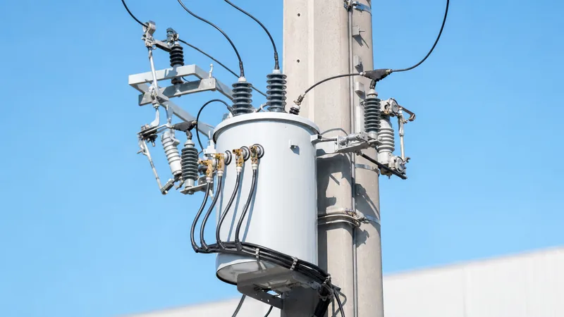
Because the unit is suspended on an overhead utility pole, weight and volume optimisation are primary design constraints. The enclosing tank is constructed from mild steel or stainless steel (grades 304 or 316 for coastal, corrosive environments) and treated with multi-coat electrostatic powder or hot-dip galvanised paint finishes. Tanks incorporate external cooling fins or corrugations for mineral oil natural air natural (ONAN) thermal dissipation. Standard accessories fitted directly to the tank wall include outdoor porcelain or polymer high-voltage (HV) bushings, low-voltage (LV) spade or stud terminals, a pressure relief device (PRD) calibrated to release excessive internal pressure between 35 kPa and 70 kPa, an oil level gauge, lifting lugs, and upper and lower pole-mounting brackets conforming to ANSI C57.12.20 bolt-hole spacing standards.
Technical Specifications and Standard Ratings
Standard ratings for three phase pole mounted units range between 30 kVA and 500 kVA, accommodating standard overhead distribution system voltages worldwide. When loads exceed 500 kVA, excessive weight typically dictates ground-level installations, as covered in our guide to the 3 phase pad mounted transformer. The table below outlines typical mechanical and electrical parameters for 50 Hz and 60 Hz pole-mounted distribution units.
| Rated Power (kVA) | Primary Voltage (kV) | Secondary Voltage (V) | Impedance (%Z at 75°C) | Approx. Weight (kg) | Basic Impulse Level HV (kV BIL) |
|---|---|---|---|---|---|
| 30 | 11 / 13.8 / 22 | 400 / 415 / 480Y/277 | 3.50 – 4.00 | 320 | 75 / 95 / 125 |
| 50 | 11 / 13.8 / 24.94 | 400 / 415 / 480Y/277 | 3.50 – 4.00 | 440 | 75 / 95 / 150 |
| 75 | 11 / 13.8 / 34.5 | 400 / 415 / 208Y/120 | 4.00 – 4.50 | 580 | 75 / 95 / 170 |
| 100 | 11 / 13.8 / 34.5 | 400 / 415 / 480Y/277 | 4.00 – 4.50 | 710 | 95 / 110 / 170 |
| 160 | 11 / 22 / 33 | 400 / 415 | 4.00 – 4.50 | 950 | 95 / 125 / 170 |
| 250 | 11 / 22 / 33 | 400 / 415 / 480Y/277 | 4.50 – 5.00 | 1,320 | 95 / 125 / 170 |
| 315 | 11 / 22 / 33 | 400 / 415 | 4.50 – 5.00 | 1,580 | 95 / 125 / 170 |
| 500 | 11 / 22 / 34.5 | 400 / 415 / 480Y/277 | 5.00 – 5.75 | 2,250 | 95 / 125 / 170 |
Full-load secondary current is calculated using the standard three-phase power formula: I = S / (√3 × V), where S represents rated apparent power in kVA and V represents line-to-line voltage in kV. For a 250 kVA transformer delivering a 400 V line-to-line output, full-load secondary current equals 250 / (1.732 × 0.400) = 360.85 A. Determining exact sizing requirements for facility demand profile calculations can be verified using a dedicated transformer sizing calculator.
Single Three-Phase Unit vs Three-Phase Bank of Single Units
Network distribution engineers choose between installing a single integrated three-phase unit or banking three separate single-phase transformers onto a shared pole cluster. A single integrated three phase pole mounted transformer delivers a compact visual footprint, reduces overall weight by 15% to 25% compared to three discrete units, eliminates complex exterior interconnection wiring, and exhibits lower total core losses because of its unified magnetic circuit. However, a catastrophic winding failure in a single three-phase unit requires lifting the entire assembly down from the pole, requiring an outage for all three phases.
Conversely, banking three single-phase units on a pole-mounted bracket cluster (or crossarm) allows utilities to replace only the faulted individual tank during maintenance, significantly reducing spare inventory handling. Furthermore, an open-delta bank configuration allows utilities to run two single-phase transformers to serve three-phase loads at 57.7% of the total bank rating under emergency situations. Despite these operational flexibilities, banked installations require more mounting clearance, place asymmetrical transverse mechanical loads on utility poles, and introduce higher risk of wiring errors across the jumper array.
Winding Configurations and Vector Groups
Standard winding configurations for three phase pole mounted units connect the medium-voltage primary in Delta and the low-voltage secondary in Grounded Wye (Star). Under IEC standards, this corresponds to vector groups Dyn11 or Dyn1, where the secondary line-to-neutral voltage leads (Dyn11) or lags (Dyn1) the primary line-to-line voltage by 30 electrical degrees. The Delta primary traps third-harmonic currents within the closed loop, preventing harmonic distortion from propagating into the upstream medium-voltage utility grid.
The secondary Wye connection provides an accessible neutral bushing brought out externally (typically marked X0). Grounding this neutral terminal establishes a stable zero-voltage reference, provides phase-to-neutral voltage for lighting and single-phase auxiliary loads (such as 230 V on a 400/230 V network, or 277 V on a 480Y/277 V system), and facilitates the return path for line-to-ground fault currents required to operate downstream protective circuit breakers. For applications requiring complete grounding analysis across delta-wye designs, consult our detailed delta y transformer guide.
Installation, Mounting, and Protection Procedures
Mounting a three-phase unit on an overhead structure requires careful verification of pole class, soil foundation bearing capacity, and electrical clearance limits. Follow this sequential engineering procedure for a compliant installation:
- Pole selection and foundation assessment: Calculate combined vertical deadweight and horizontal wind-loading forces on the utility pole in accordance with the National Electrical Safety Code (NESC) or local utility structural rules. Units weighing over 1,000 kg generally require a Class 1 or Class 2 timber pole, spun concrete pole, or an H-frame two-pole platform structure.
- Bracket positioning and mechanical hoisting: Fasten heavy-duty galvanised steel pole bands or through-bolts through the pre-drilled pole gains. Rig the transformer using the designated lifting lugs on the tank wall, maintaining an lifting sling angle not exceeding 60 degrees from horizontal to prevent crushing the tank lid, and torque structural bolts to manufacturer specifications.
- Surge arresters and primary cutouts: Mount metal-oxide surge arresters (MOVs) directly adjacent to the high-voltage bushings on crossarms, keeping lead lengths under 300 mm to minimise inductive surge impedance (L × di/dt). Install fused drop-out cutouts upstream on the crossarm to clear high-magnitude internal phase faults and provide manual visible disconnection.
- Grounding and secondary bonding: Drive copper-bonded earth rods to achieve a system earthing resistance below 5 Ω (or 10 Ω depending on local utility regulations). Interconnect the transformer tank ground pad, the lightning arrester ground bus, and the low-voltage neutral bushing (X0) to create an effective solid ground reference.
- Cabling and pre-energisation testing: Connect overhead drop conductors using bimetallic compression lugs to prevent galvanic corrosion between copper bushings and aluminium conductors. Verify insulation resistance using a 2.5 kV DC megohmmeter (HV to LV, HV to Ground, LV to Ground) and confirm voltage turns ratio before closing the cutouts.
Next steps: specifying and sourcing
When preparing procurement specifications for an overhead distribution project, compile detailed engineering criteria including system nominal voltage, required Basic Impulse Level (BIL), secondary utilisation voltage, ambient temperature range, and maximum allowable no-load and load losses under IEEE C57.12.00 or IEC 60076. Explore our engineering catalogue of pole-mounted transformers and oil-immersed transformers to review standard construction designs, thermal classes, and tank accessories. For direct engineering support, custom vector groups, tender compliance reviews, and commercial manufacturing proposals, submit your technical schedule directly through our transformer quotation request page.
Frequently asked questions
What is the maximum kVA for a 3 phase pole mounted transformer?
The practical upper limit for a single 3 phase pole mounted transformer is typically 500 kVA. Above 500 kVA, the combined weight of the core, copper windings, and dielectric oil exceeds 2,200 kg, which overstresses single-pole structural capacity and demands either an H-frame platform or a ground-level pad-mounted installation.
How does a three-phase pole mounted unit differ from three banked single-phase transformers?
A single three-phase pole mounted unit contains all three phase windings inside one shared oil tank, offering lower total weight, smaller dimensions, and lower core losses. Three banked single-phase transformers require more crossarm space and complex exterior wiring, but allow independent replacement of a single damaged phase without replacing the entire installation.
What primary winding connection is most common for pole-mounted three-phase transformers?
Delta connection is the most common primary winding configuration, paired with a Grounded Wye secondary (Dyn11 or Dyn1). The primary Delta winding traps zero-sequence harmonic currents within the closed loop, isolating third harmonics from the overhead distribution network and providing stable line-to-neutral voltages on the low-voltage output.
What protection devices are required for a 3 phase pole mounted transformer?
Standard protection requires high-voltage fused drop-out cutouts for short-circuit clearance and physical line disconnection, combined with metal-oxide surge arresters mounted close to the HV bushings for lightning overvoltage suppression. Internally, the tank features a mechanical pressure relief valve to vent excessive gases safely during sustained overcurrent or internal flashovers.
What dielectric fluid is used in three phase pole mounted transformers?
Most three-phase pole-mounted transformers utilise uninhibited or inhibited mineral insulating oil conforming to IEC 60296 or ASTM D3487. For installations situated in environmentally sensitive zones, national parks, or dense urban corridors, natural ester fluids (vegetable oils) compliant with IEEE C57.147 are frequently specified due to their high fire point and biodegradability.
Tags: 3 phase pole mounted transformer three phase pole mounted transformer pole mounted transformer distribution transformer transformer configurations


