Key takeaways
- Electrical distribution equipment encompasses all medium- and low-voltage assemblies that safely route, isolate, and step down power from the intake point to downstream branch circuits.
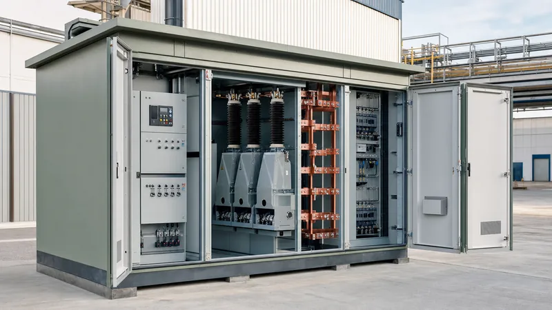
- Prefabricated box-type substations package MV switchgear, distribution transformers, and LV switchboards into an integrated, factory-tested envelope governed by IEC 62271-202.
- Prospective short-circuit current must dictate the thermal and dynamic withstand ratings of copper busbars, circuit breakers, and enclosure framing under IEC 61439-1.
- Internal Arc Classification (IAC AFLR) validates that electrical power distribution equipment protects personnel against explosive failure modes during operational access.
- Accurate factory derating calculations for ambient temperature and enclosure ventilation prevent premature thermal tripping of low-voltage air circuit breakers.
Quick answer: Electrical distribution equipment comprises the medium-voltage switchgear, step-down transformers, low-voltage distribution boards, and protective relays that receive utility power and route it safely to end-use loads. In modern industrial and utility networks, these components are frequently integrated inside factory-engineered box-type substations to minimise on-site assembly, guarantee type-tested arc safety, and reduce spatial footprints.
Industrial plants, commercial complexes, and renewable energy facilities rely on a structured hierarchy of switchgear and sub-assemblies to maintain operational continuity. As network capacities grow, engineers must evaluate short-circuit ratings, insulation levels, and thermal boundaries before issuing procurement technical schedules. Consulting our detailed guide to electric power distribution engineering provides foundational insight into single-line diagrams, while this guide examines physical equipment selection, enclosure integration, and rating verification.
Core Types of Electrical Distribution Equipment in Box Substations
Box-type substations house three primary functional assemblies: medium-voltage (MV) intake gear, an intermediate transformer, and low-voltage (LV) feeder switchboards.
The medium-voltage compartment usually features a ring main unit (RMU) or metal-enclosed switchgear operating between 11 kV and 33 kV. These assemblies employ vacuum circuit breakers (VCBs) or load break switches insulated with dry air, solid dielectric materials, or gas to interrupt short-circuit faults. For detailed guidance on modular layouts, review our unit substation engineering guide.
The transformer section houses either an oil-immersed unit with corrugated fins or a cast-resin dry-type unit. The selected unit steps primary voltages down to standard utilisation levels (such as 400 V or 480 V three-phase). Oil-immersed units provide high thermal dissipation for outdoor box substations, whereas cast-resin units eliminate combustible fluids near critical infrastructure.
The low-voltage compartment houses incoming air circuit breakers (ACBs), moulded-case circuit breakers (MCCBs), power factor correction capacitors, and metering instruments. Built to compliant separation forms under IEC 61439-2, this section partitions busbars from functional breaker units to guarantee operator safety during routine maintenance.
Standards and Safety Ratings for Electrical Power Distribution Equipment
International safety and performance compliance protects personnel from catastrophic arc events and ensures that switchgear withstands mechanical shock under heavy faults.
For prefabricated modular enclosures, IEC 62271-202 specifies design parameters, ingress ratings, and the Internal Arc Classification (IAC). When specifying electrical power distribution equipment, engineers must require an IAC rating of AFLR (Access for Front, Lateral, and Rear) tested to fault currents up to 20 kA or 25 kA for 1 second. This classification guarantees that gasses vent vertically or via controlled exhaust ducts away from technicians.
Low-voltage distribution sections must comply with IEC 61439-1 and IEC 61439-2, which supersede older type-tested assembly (TTA) frameworks. Key requirements mandate proof of temperature-rise limits (Clause 10.10) and dielectric clearance verification (Clause 10.9). In North American jurisdictions governed by IEEE C37.20.2 and UL 891, assemblies must sustain designated short-circuit withstand ratings without mechanical deformation of the bus support insulators or weld points.
Air-Insulated vs Gas-Insulated vs Prefabricated Equipment
Selecting the optimal equipment morphology depends on site footprint limits, environmental contamination, and life-cycle maintenance budgets.
| Parameter | Air-Insulated Switchgear (AIS) | Gas-Insulated Switchgear (GIS) | Box-Type Packaged Substation |
|---|---|---|---|
| Footprint Ratio | 1.0 (Baseline) | 0.35 - 0.45 | 0.60 - 0.70 (Self-contained) |
| Rated Voltage Range | 3.3 kV - 36 kV | 11 kV - 145 kV+ | 6 kV - 40.5 kV |
| Protection from Environment | IP3X - IP4X (Indoor required) | Hermetically sealed (high ingress protection) | Outdoor rated (IP43 to IP54) |
| BIL Withstand (at 24 kV) | 125 kV peak | 125 kV peak | 125 kV peak (Factory coordinated) |
| Routine Maintenance Interval | 1 - 2 Years | 5 - 10 Years | 2 - 3 Years |
| Capital Cost Index | 1.0 (Lowest) | 1.6 - 2.2 | 1.2 - 1.4 (Installed basis) |
While AIS delivers lower upfront capital expenditure, it requires climate-controlled switchrooms. Packaged outdoor box substations eliminate civil building construction costs by placing the MV switchgear, transformer, and LV boards into a single pre-wired enclosure. Review the technical differences in our dedicated MV switchgear engineering guide before drafting procurement specifications.
Engineering Calculation: Busbar Short-Circuit Withstand Sizing
Busbars in low-voltage electrical distribution equipment must endure both thermal heating and mechanical electrodynamic stresses during through-fault conditions.
Consider an outdoor box-type substation feeding a 400 V switchboard directly from a 2,000 kVA, 11 kV to 0.4 kV distribution transformer with an impedance voltage ($U_k$) of 6.0%. Calculate the prospective short-circuit current and determine the minimum cross-sectional area of the main copper busbar to withstand a 1.0-second fault without exceeding insulation thermal thresholds.
Step 1: Calculate transformer rated secondary current ($I_n$):
$$I_n = \frac{S_n}{\sqrt{3} \times U_n} = \frac{2000\text{ kVA}}{\sqrt{3} \times 0.4\text{ kV}} = 2886.8\text{ A}$$
Step 2: Determine prospective symmetrical short-circuit current ($I_{sc}$):
$$I_{sc} = \frac{I_n}{U_k / 100} = \frac{2886.8\text{ A}}{0.06} = 48113\text{ A} \approx 48.1\text{ kA}$$
Step 3: Size the copper busbar thermal cross-section ($S$) using the adiabatic formula per IEC 60865-1:
$$S \ge \frac{I_{sc} \times \sqrt{t_k}}{k}$$
Where fault duration $t_k = 1.0\text{ s}$, and the material constant $k$ for bare copper transitioning from an initial operating temperature of 70°C to an allowable fault limit of 200°C is 176 $\text{A}\cdot\text{s}^{1/2}/\text{mm}^2$.
$$S \ge \frac{48113 \times \sqrt{1.0}}{176} = 273.4\text{ mm}^2$$
While $273.4\text{ mm}^2$ satisfies purely adiabatic thermal heating, the busbar must also carry the continuous 2,886 A load current and resist lateral electromagnetic deflection under peak peak fault currents ($I_p \approx 48.1 \times 2.2 = 105.8\text{ kA}$). Consequently, standard design selects two or three parallel $100\text{ mm} \times 10\text{ mm}$ copper bars per phase (providing 2,000 to $3,000\text{ mm}^2$ total cross-section) mounted on short-circuit tested porcelain or cycloaliphatic resin insulators spaced at 300 mm intervals.
Pre-Commissioning Inspection Checklist for Distribution Assemblies
A disciplined pre-commissioning inspection ensures that electrical distribution equipment has suffered no transit damage, loose terminations, or insulation degradation.
- Verify environmental containment: confirm the box substation foundation slab is sealed against water ingress, cable entry glands are clamped, and vermin screens are intact.
- Complete insulation resistance testing: apply a 2,500 V DC megohmmeter to MV switchgear windings and phase-to-earth points; apply a 1,000 V DC megohmmeter across LV busbar phases per IEC 61439 standards. Minimum values should exceed 100 MΩ for MV and 10 MΩ for LV circuits.
- Perform contact resistance micro-ohm measurements: verify main circuit breaker contact resistance across vacuum interrupters and air circuit breakers against manufacturer factory test certificates (typically under 40 micro-ohms).
- Verify torque specifications: check mechanical bolting across copper busbar overlap joints using a calibrated torque wrench, applying torque-seal lacquer across nuts and Belleville conical washers.
- Perform functional protection testing: inject secondary current into protective relays (50/51 overcurrent, 50N/51N earth fault) to verify trip thresholds, auxiliary contact outputs, and shunt trip actuation times under 40 milliseconds.
Common Specification Errors in Equipment Procurement
Inadequate thermal derating and insufficient space for medium-voltage cable bending represent the most frequent oversights during switchgear procurement.
Placing electrical power distribution equipment inside compact outdoor kiosks alters internal convective cooling. Specifiers frequently order standard indoor-rated circuit breakers without applying ambient temperature derating factors. If summer temperatures within an enclosed steel box reach 50°C, a 3,200 A ACB rated at 40°C must be derated by approximately 10% to 15% (to roughly 2,750 A continuous) unless forced cooling fans with monitored thermostatic controls are engineered into the roof plenum.
Another common mistake involves cable termination compartments. Modern single-core 33 kV cross-linked polyethylene (XLPE) cables with large cross-sections (such as $630\text{ mm}^2$) require significant bending radiuses—often 15 to 20 times the overall cable diameter. When switchgear cable boxes are designed with shallow depths, termination lugs experience mechanical shear stress, which damages bushing seals and eventually precipitates dielectric flashover.
Next steps: specifying and sourcing
When preparing requests for quotation for factory-assembled distribution substations and switchgear, compile your complete single-line diagram, prospective fault levels (kA / 1 s), site ambient extremes, and preferred Form of separation. Our engineering team designs and manufactures type-tested transformer substations, HV/LV switchgear, and outdoor pad-mounted transformers fully compliant with IEC and IEEE benchmarks. For project-specific designs, thermal calculations, or formal tenders, submit your requirements via our quotation inquiry page or reach out directly through our technical contact desk.
Frequently asked questions
What is included in electrical distribution equipment?
Electrical distribution equipment includes medium-voltage switchgear, distribution transformers, low-voltage switchboards, bus ducts, motor control centres, and protection relays. Together, these devices receive incoming power from transmission or distribution networks and route it safely to end-use industrial, commercial, or residential circuits.
What is the difference between transmission and distribution equipment?
Transmission equipment operates at high voltages (typically 69 kV to 765 kV) to transport bulk electricity over long distances between power plants and grid substations. Distribution equipment operates at medium and low voltages (typically 33 kV down to 400 V) to step down, isolate, and route power to local consumers.
How does a box-type substation protect electrical distribution equipment?
A box-type substation encloses transformers and switchgear inside an outdoor-rated, weatherproof steel or concrete enclosure. It provides mechanical ingress protection (IP43 to IP54), integrated fire containment, ventilation plenums, and internal arc blast venting channels to protect both the internal apparatus and passing personnel.
Why is short-circuit withstand rating critical for distribution switchboards?
Short-circuit withstand ratings define the maximum fault current that distribution equipment can safely carry for a set period (typically 1 or 3 seconds) without suffering physical destruction from electromagnetic repulsion or thermal conductor melting. Insufficient withstand ratings cause catastrophic switchboard explosions during upstream fault conditions.
How often should electrical distribution equipment be inspected?
Visual inspections, environmental cleanliness checks, and thermal imaging audits should be conducted every 6 to 12 months. Comprehensive electrical testing—including breaker timing, insulation resistance, contact micro-ohm checks, and secondary relay injection—should occur every 3 to 5 years depending on operating conditions.
Tags: electrical distribution equipment electrical power distribution equipment switchgear box-type substation distribution engineering


