Key takeaways
- Industrial circuit breakers must be specified by both ultimate short-circuit breaking capacity (Icu) and service breaking capacity (Ics) per IEC 60947-2 Clause 4.3.5.
- Air circuit breakers (ACBs) provide selective coordination via short-time withstand current (Icw) ratings, making them the standard choice for main low-voltage incoming feeders up to 6300 A.
- Moulded case circuit breakers (MCCBs) handle distribution circuits from 16 A to 1600 A, offering compact footprints with adjustable electronic trip units (LSIG).
- For motor and transformer inrush applications, sizing must account for peak asymmetrical making current (Icm), which is typically 2.1 to 2.2 times the symmetrical RMS breaking capacity.
- Factory audits of circuit breaker suppliers should mandate routine dielectric, contact resistance, and tripping characteristic tests witnessed under IEC 60947-2 or IEEE C37.50.
Quick answer: Industrial circuit breakers are mechanical switching devices engineered to make, carry, and break currents under normal circuit conditions and interrupt severe fault currents, such as short circuits and overloads, under specified abnormal conditions. They span low-voltage moulded case and air circuit breakers up to medium-voltage vacuum interrupters, rated to handle currents from 16 A to over 6300 A at fault levels up to 150 kA.
In heavy commercial and manufacturing infrastructure, reliable fault clearance protects capital assets, preserves operational uptime, and ensures personnel safety. Selecting appropriate industrial circuit breakers requires rigorous alignment between network prospective fault levels, thermal continuous ratings, and protective trip curves. Whether engineers are modernising an existing motor control centre or configuring switchboards for a continuous-process plant, understanding the mechanical and electrical boundaries of each breaker frame is essential for long-term plant resilience. For an overview of how these units integrate into complete assemblies, consult our guide to electrical switchgear systems.
Core Types of Industrial Circuit Breakers: ACB, MCCB, and VCB
Industrial circuit breakers fall into three primary categories based on voltage class, continuous current rating, and arc interruption medium: Moulded Case Circuit Breakers (MCCBs), Air Circuit Breakers (ACBs), and Vacuum Circuit Breakers (VCBs).
Moulded Case Circuit Breakers (MCCBs) house the current-carrying paths, trip mechanisms, and arc chutes within an integral glass-filled polyester or thermoset casing. Typically applied from 16 A up to 1600 A at voltages up to 690 V AC, MCCBs serve as branch and sub-distribution protection. Modern industrial MCCBs feature interchangeable electronic trip units providing adjustable long-time, short-time, instantaneous, and ground-fault (LSIG) protection.
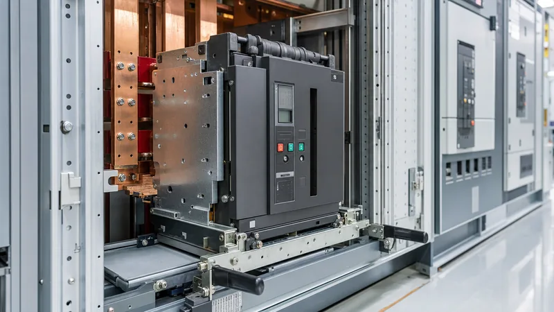
Air Circuit Breakers (ACBs) utilise open-frame steel construction with high-performance arc chutes operating in ambient air. Ranging from 630 A to 6300 A, ACBs are the primary choice for main incoming switchboards and tie breakers. Their key advantage is a defined short-time withstand current (Icw), which enables full downstream time-current discrimination without tripping the main incomer prematurely during downstream faults. Further details on breaker frames within distribution systems are outlined in our switchgear breaker ratings and selection guide.
Vacuum Circuit Breakers (VCBs) dominate medium-voltage industrial distribution from 3.3 kV up to 40.5 kV. Arc interruption occurs within a hermetically sealed ceramic vacuum interrupter bottle where metal vapour condenses rapidly upon contact separation at current zero. VCBs offer mechanical endurance often exceeding 10,000 to 30,000 operations, making them ideal for frequent switching duties, large motor protection, and substation primary distribution. For detailed internal mechanics of medium-voltage units, refer to our vacuum circuit breaker guide.
Critical Electrical Ratings: Understanding Icu, Ics, Icw, and Icm
Selecting industrial circuit breakers requires decoding standardised nameplate ratings defined by IEC 60947-2 (Low-Voltage Switchgear and Controlgear) and IEEE C37.13 / C37.04 for ANSI installations.
- Rated Ultimate Short-Circuit Breaking Capacity (Icu): The maximum fault current (in kA RMS) the breaker can interrupt twice (test sequence: Open - Time Delay - Close/Open) at a specified voltage. After this test, the breaker is not required to carry its rated continuous current safely without maintenance.
- Rated Service Short-Circuit Breaking Capacity (Ics): The fault current level the breaker can clear three times (O - t - CO - t - CO) and retain full operational integrity, including normal temperature rise and dielectric withstand. Sourcing industrial circuit breakers with Ics = 100% Icu ensures high operational reliability in critical process industries where downtime cannot be tolerated.
- Rated Short-Time Withstand Current (Icw): The maximum current a Category B breaker can carry for a defined duration (typically 1.0 or 3.0 seconds) without contacts welding or sustaining mechanical destruction. This rating defines selective coordination capability.
- Rated Short-Circuit Making Capacity (Icm): The peak prospective current the device can close onto without contact bounce destroying the mechanism. Per IEC 60947-2 Clause 4.3.6.1, for an Icu exceeding 50 kA, the ratio of Icm to Icu is typically 2.2:1 (reflecting peak asymmetrical current under low power factor conditions).
Specifying engineers must verify these values against the prospective fault levels established by short-circuit calculations at the switchboard busbars, taking into account upstream utility fault levels and on-site motor contribution.
Worked Example: Sizing an Incoming ACB for a 1600 kVA Transformer
To demonstrate correct sizing calculations for industrial circuit breakers, consider an industrial plant incoming switchboard fed by a 1600 kVA dry-type transformer with a secondary voltage of 400 V (three-phase, 50 Hz) and an impedance voltage (%Z) of 6.0%.
Step 1: Calculate full load continuous current (Iflc)
Using the three-phase power formula:
Iflc = S / (√3 × Vline)
Iflc = 1,600,000 VA / (1.732 × 400 V) = 2,309.4 A
To avoid thermal nuisance trips and accommodate planned overload capacity (such as forced-air cooling on the transformer), an incoming air circuit breaker with a nominal frame rating (In) of 2500 A or 3200 A is selected. We select a 2500 A frame with an electronic trip unit set to Ir = 2400 A.
Step 2: Calculate prospective symmetrical fault current (Isc) at secondary terminals
Assuming an infinite upstream utility bus for worst-case analysis:
Isc = Iflc / (%Z / 100)
Isc = 2309.4 A / 0.06 = 38,490 A ≈ 38.5 kA RMS
Step 3: Account for motor back-feed contribution
Industrial plants run substantial induction motor loads. Assuming 60% of the plant load consists of running induction motors, their momentary short-circuit contribution during the first few cycles adds approximately 4 times their full-load current (approx. 5.5 kA).
Itotal_fault = 38.5 kA + 5.5 kA = 44.0 kA RMS
Step 4: Select breaker ratings with safety margin
Applying a minimum safety margin of 20% to account for grid stiffness increases:
Target breaking capacity ≥ 44.0 kA × 1.2 = 52.8 kA
Consequently, an ACB with an Icu of 65 kA (at 415 V) and Ics = 100% Icu (65 kA) must be specified. The rated short-time withstand (Icw) must be rated at 65 kA for 1.0 second to ensure fault clearance selectivity with downstream 250 A to 630 A MCCB branch breakers. Design guidelines for matching panel structural ratings with these calculations can be found in our IEC 61439 low-voltage switchgear guide.
Industrial Circuit Breakers Comparison Matrix
A technical comparison across primary breaker categories simplifies equipment matching during preliminary engineering and front-end engineering design (FEED) stages.
| Breaker Category | Rated Voltage (Ur) | Rated Current (In) | Typical Breaking Capacity (Icu) | Tripping Technology | Primary Application |
|---|---|---|---|---|---|
| Miniature Circuit Breakers (MCB) | 230 V / 400 V AC | 0.5 A to 125 A | 6 kA to 25 kA | Thermal-magnetic fixed | Control circuits, instrumentation, lighting panels |
| Moulded Case Breakers (MCCB) | Up to 690 V AC | 16 A to 1600 A | 25 kA to 150 kA | Thermal-magnetic or Electronic (LSIG) | Motor feeders, sub-distribution boards, secondary mains |
| Air Circuit Breakers (ACB) | Up to 1000 V AC | 630 A to 6300 A | 50 kA to 150 kA (Icw = Ics) | Microprocessor trip unit with communication | Main substation incomers, bus couplers, large drives |
| Vacuum Circuit Breakers (VCB) | 3.3 kV to 40.5 kV | 630 A to 4000 A | 20 kA to 50 kA (sym) | External numerical protection relays (50/51, 50N/51N) | Medium-voltage switchgear, incoming feeders, arc furnaces |
Evaluating Circuit Breaker Suppliers: Quality Audits and Type Testing
Qualifying industrial circuit breaker suppliers requires rigorous examination of independent type-test certifications, manufacturing automation, and supply chain integrity rather than relying solely on datasheets.
When auditing prospective circuit breaker suppliers, engineering procurement teams must demand third-party type test certificates issued by accredited laboratories (such as ASTA, KEMA, or CESI). These tests verify performance under extreme stress conditions, including temperature-rise limits under full load (IEC 60947-2 Clause 8.3.3.3), short-circuit making and breaking capabilities, and mechanical endurance tests without lubrication or contact replacement.
Essential routine tests conducted on 100% of manufactured units at the factory include:
- Dielectric withstand verification: Testing power frequency insulation across open contacts and between phase-to-phase and phase-to-earth terminals at 2.5 kV to 3.5 kV for 60 seconds.
- Contact resistance measurement: Utilizing micro-ohmmeters (typically injecting 100 A DC) to verify low millivolt drop across main contacts, preventing terminal overheating.
- Calibration verification of trip mechanisms: Secondary current injection testing across the entire characteristic curve, validating pickup thresholds and time delays for long-time (L), short-time (S), instantaneous (I), and ground-fault (G) functions.
- Mechanical operational cycling: Minimum of 25 open/close/charge operations on motorised mechanisms, confirming correct auxiliary switch signalling, interlock integrity, and anti-pumping relay performance.
Procurement and RFQ Specification Checklist
An incomplete technical schedule leads to project delays, change orders, or delivery of equipment ill-suited for the operating environment. Electrical engineers can use the following technical checklist when drafting request-for-quotation (RFQ) packages for industrial circuit breakers:
- Operating voltage and network frequency: Nominal voltage (e.g., 400 V, 480 V, 690 V), maximum continuous operating voltage, and frequency (50 Hz or 60 Hz).
- System earthing arrangement: TN-S, TN-C, TT, or IT earthing, which dictates pole configuration (3-pole vs 4-pole breakers and neutral sensing).
- Fault levels: Specified Icu, Ics (demanding 100% Ics where critical continuity is required), and minimum 1.0 s short-time withstand current (Icw).
- Environmental constraints: Ambient operating temperature range (-5°C to +40°C or +55°C without derating), altitude (>1000 m requires voltage and current derating factors per IEC 60947-1), and relative humidity / seismic zone requirements.
- Mounting style: Fixed-mounted vs draw-out (withdrawable). Draw-out execution provides safety shutters, test/disconnected positions, and rapid replacement during plant turnarounds.
- Protection and control architecture: Electronic trip unit features (ammeter display, harmonic analysis, thermal memory), auxiliary contact quantities (NO/NC), shunt trip and undervoltage release coils, and industrial communication protocols (Modbus RTU, Profinet, IEC 61850).
- Mechanical interlocks: Key interlocks (Castell/Ronif), cable interlocks, or door-interlock mechanisms for source-changeover schemes and dual-incomer bus-tie setups.
Next steps: specifying and sourcing
When specifying industrial circuit breakers for your switchboard projects, substation builds, or plant expansions, early coordination with an established manufacturing partner eliminates sizing bottlenecks and coordination errors. Prepare your single-line diagrams, target fault levels, continuous load currents, and required trip unit protection curves. Explore our engineered HV and LV switchgear assemblies or review our integrated compact transformer substations to see how breakers integrate into full turnkey distributions. Submit your single-line diagram and tender schedules via our quotation inquiry page for rapid technical assessment and commercial pricing.
Frequently asked questions
What is the difference between an ACB and an MCCB?
An Air Circuit Breaker (ACB) features an open-frame steel design rated for higher continuous currents (up to 6300 A) and possesses a high short-time withstand rating (Icw) for upstream selectivity. A Moulded Case Circuit Breaker (MCCB) houses its mechanism within an enclosed insulating body, typically protecting branch circuits up to 1600 A with a focus on compact installation.
Why is the Ics rating critical when choosing industrial circuit breakers?
The service breaking capacity (Ics) indicates the fault current a breaker can interrupt multiple times while remaining fully operational without contact replacement. Specifying Ics = 100% Icu ensures the breaker can clear a severe short circuit and be re-closed immediately, preventing prolonged plant downtime.
When should draw-out circuit breakers be specified instead of fixed units?
Draw-out circuit breakers should be specified in continuous-process facilities, data centres, and critical infrastructure where downtime during maintenance or replacement cannot be tolerated. A draw-out breaker can be racked out to an isolated test position or completely removed in minutes without disturbing main busbar terminations.
How does ambient temperature affect industrial circuit breaker ratings?
Industrial circuit breakers are standardly calibrated for operation at 40°C ambient temperature. Operating in environments above 40°C requires derating the continuous current rating (In) per manufacturer thermal-magnetic or electronic derating curves to prevent premature nuisance tripping and terminal overheating.
What protection functions does an LSIG electronic trip unit provide?
An LSIG trip unit provides Long-time protection (L) for continuous overload clearance, Short-time delay (S) for timed fault coordination, Instantaneous tripping (I) for high-magnitude short circuits, and Ground-fault protection (G) to clear low-level phase-to-earth faults that could cause arc-flash hazards.
Tags: industrial circuit breakers circuit breaker suppliers switchgear components air circuit breaker molded case circuit breaker


