Key takeaways
- A microgrid energy management system executes real-time tertiary optimisation, active power dispatch, and demand management across local generation assets in compliance with IEEE 2030.7.
- Control hierarchies divide into primary millisecond-level droop response, secondary sub-second voltage and frequency restoration, and tertiary multi-minute economic scheduling.
- Modern microgrid management systems rely on deterministic industrial fieldbuses, utilising IEC 61850 GOOSE messaging alongside IEC 60870-5-104 or Modbus TCP/IP for upstream SCADA integration.
- Seamless islanding and black-start coordination require the microgrid control software to switch battery power conversion systems from grid-following to grid-forming mode in under 16 milliseconds.
- Economic dispatch algorithms calculate optimal unit commitment using rolling 24-hour solar generation forecasts, time-of-use utility tariffs, and real-time battery state-of-charge constraints.
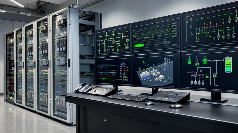
Quick answer: A microgrid energy management system (EMS) is a software- and hardware-driven supervisory control platform that coordinates distributed energy resources (DERs), battery storage, and electrical loads to maintain power quality, minimise energy costs, and ensure uninterrupted power during grid disturbances.
Industrial microgrids combine renewable generation, thermal gensets, battery storage systems, and medium-voltage switchgear into an autonomous electrical network. Managing these intermittent assets requires higher-level decision logic than standard industrial supervisory control and data acquisition (SCADA) offers. The EMS continuously gathers real-time telemetry from power meters, protection relays, and inverter systems. It executes mathematical optimisation algorithms to manage power flows, shave peak demand charges, and schedule unit commitments while safeguarding electrical equipment from thermal overload and frequency deviations. For foundational system topology, refer to our Microgrid Definition: Engineering Guide to Power Systems.
Hierarchical Architecture: IEEE 2030.7 Control Layers
A standardised microgrid energy management system operates across three distinct functional tiers defined by the IEEE 2030.7 standard for microgrid control systems.
To avoid control instability and hunting between paralleled sources, engineers segregate automation functions based on operational response speed:
- Primary Control (Local / Millisecond Domain): Embedded directly within individual inverter firmware and generator governors. It executes autonomous droop control (P-f and Q-V droop) within 2 ms to 20 ms, maintaining immediate active and reactive balance without external communications.
- Secondary Control (Microgrid Controller / Sub-second Domain): Operates via the dedicated microgrid controller (typically a hardened industrial programmable automation controller, or PAC) cycling at 50 ms to 500 ms intervals. It restores system frequency and nominal voltage to target setpoints following load steps and manages seamless synchronisation across circuit breakers.
- Tertiary Control (Microgrid Energy Management / Minutes to Hours Domain): Hosts the higher-level microgrid management software. Tertiary algorithms analyse historical consumption, weather forecasts, time-of-use tariffs, and battery state-of-health (SoH) metrics over rolling 15-minute to 24-hour windows to formulate economic dispatch profiles.
By delegating sub-cycle safety interlocks to the switchgear protection relays and inverter controls, the tertiary microgrid energy management platform focuses entirely on resource optimisation, load scheduling, and coordinated carbon reduction.
Core Functions of Microgrid Control Software
Modern microgrid control software executes core functions that bridge real-time electrical safety with multi-market economic optimisation.
First, the platform executes active and reactive power dispatch based on real-time cost curves. If grid import tariffs peak, the software commands the battery Power Conversion System (PCS) to discharge, maintaining the site demand below utility penalty thresholds as covered in our guide on peak shaving with battery energy storage.
Second, the platform controls the transition between grid-connected and islanded operating states. Upon sensing an upstream substation voltage collapse via an undervoltage (27) or directional overcurrent (67) trigger from the protection relay, the secondary microgrid management system commands the point of common coupling (PCC) vacuum circuit breaker to open. It simultaneously commands the primary energy storage inverter to switch from current-source (grid-following) mode to voltage-source (grid-forming) mode within 16 milliseconds to prevent critical bus collapse.
Third, resynchronisation logic handles the return to normal utility operations. The software monitors the voltage magnitude difference (ΔV < 3%), frequency deviation (Δf < 0.1 Hz), and phase angle displacement (Δθ < 5°) across the open PCC breaker in accordance with IEEE 1547 Table 5 before issuing a close command to avoid shaft torque damage to rotating assets.
Communication Protocols and Substation Integration
Deterministic communications form the operational backbone of an integrated microgrid energy management system inside medium-voltage substations.
Substation automation cannot rely on standard enterprise IT networks due to non-deterministic latency. Consequently, industrial installations partition microgrid communications into dedicated process and station networks, combining standard protocols tailored to specific latency requirements:
- IEC 61850 GOOSE (Generic Object Oriented Substation Events): Deployed over redundant ring networks (PRP/HSR) for high-speed interlocking, tripping, and automated transfer schemes, delivering sub-4 ms latency between switchgear intelligent electronic devices (IEDs).
- IEC 61850 MMS (Manufacturing Message Specification): Used for cyclic telemetry, measurement exchange, and diagnostic logging between substation IEDs and the secondary microgrid controller.
- Modbus TCP/IP & DNP3: Retained for legacy diesel generator controllers, chillers, and building management interfaces, polling at 100 ms to 1 s cycle times.
- IEC 60870-5-104: Primary protocol for SCADA communications between the site microgrid management platform and regional utility grid dispatchers.
Engineers must incorporate robust cybersecurity per IEC 62351, enforcing role-based access control (RBAC), TLS 1.3 encryption for upstream SCADA ports, and deep packet inspection firewalls to protect substation automation networks from malicious operational tampering.
Comparing Centralised vs Distributed Microgrid Management Software
Choosing between centralised and distributed control architectures dictates field cabling costs, hardware redundancy requirements, and operational fault tolerance.
The engineering team must select the control topology early in the design phase based on site layout, asset geographical dispersion, and operational reliability requirements.
| Evaluation Criterion | Centralised Microgrid Management | Distributed Multi-Agent Architecture | Hybrid Substation Model |
|---|---|---|---|
| Control Hardware Topology | Single redundant master PAC / server cluster | Autonomous controllers distributed at each DER node | Centralised tertiary EMS with local autonomous secondary PACs |
| Communication Bandwidth Demand | High (all raw telemetry routed to single point) | Low (peer-to-peer event-based data exchange) | Moderate (filtered telemetry to master, local peer control) |
| Single Point of Failure Vulnerability | High (requires standby server redundancy) | Extremely low (inherently resilient to node loss) | Low (local clusters continue operating if master fails) |
| Determinism & Latency | 50 ms to 200 ms overall response | 10 ms to 50 ms local response | Sub-20 ms for local safety, 1 s for tertiary updates |
| Commissioning Complexity | Moderate (linear integration and testing) | High (complex multi-agent algorithm validation) | Balanced (modular, standardized factory-acceptance) |
| Best-Fit Application | Contained industrial plant or single compound | Geographically dispersed campuses and distribution feeders | Large industrial complexes and critical unit substations |
For most commercial and industrial sites, a hybrid model offers optimal balance: critical protection tripping and islanding logic reside at the switchgear line-up, while tertiary economic algorithms reside in the main substation control room or industrial cloud server.
Worked Engineering Calculation: Sizing and Dispatch Optimisation
Dimensioning the storage asset and calculating active power dispatch parameters requires evaluating facility load profiles, photovoltaic production curves, and ramp-rate limits.
Consider an industrial facility connected at 11 kV with the following operational parameters:
- Peak site load (Pload,max): 3,500 kW
- Grid import demand charge threshold limit: 2,000 kW
- Rooftop solar PV capacity (Ppv,rated): 1,800 kWp
- Installed battery energy storage system (BESS): 2,000 kWh / 1,000 kW inverter rating
- Battery round-trip efficiency (ηbess): 88% (0.88)
- Allowable depth of discharge (DoD): 80% (usable capacity Eusable = 2,000 × 0.8 = 1,600 kWh)
At 14:00 hours, cloud cover causes solar generation to drop abruptly from 1,600 kW to 400 kW over a 60-second window, while plant manufacturing load remains constant at 3,200 kW. Without rapid intervention, utility grid import would surge to:
Pimport,uncontrolled = Pload - Ppv = 3,200 kW - 400 kW = 2,800 kW
This surge exceeds the 2,000 kW contracted maximum demand limit by 800 kW, incurring severe utility demand ratchet penalties. The microgrid management platform instantly calculates the required storage discharge setpoint:
Pbess,target = Pload - Ppv - Pgrid,max = 3,200 kW - 400 kW - 2,000 kW = 800 kW
Because the 800 kW demand is within the 1,000 kW PCS rating, the EMS commands the inverter to discharge 800 kW. To determine how long the microgrid management software can sustain this dispatch before breaching the maximum depth of discharge:
tsustainable = (Eusable × ηdischarge) / Pbess,target
Assuming single-path discharge efficiency (ηdischarge = √0.88 ≈ 0.938):
tsustainable = (1,600 kWh × 0.938) / 800 kW = 1,500.8 kWh / 800 kW = 1.876 hours (112.5 minutes)
If the solar deficit persists beyond 112 minutes, the tertiary software automatically schedules a secondary backup diesel genset start at minute 95 (allowing 10 minutes for run-up, synchronisation, and base loading) to prevent exceeding the demand ceiling or deep-cycling the battery cells.
Specification and Factory Testing Checklist for Engineers
Procuring a dependable microgrid energy management system requires a precise technical specification schedule for switchgear builders, software vendors, and EPC contractors.
- Control Response Requirements: Specify maximum latency thresholds: sub-16 ms for islanding detection, sub-100 ms for active secondary frequency response, and under 5 minutes for tertiary multi-objective dispatch updates.
- Controller Hardware Ruggedisation: Mandate industrial PAC hardware rated to IEC 61850-3 and IEEE 1613 standards for electrostatic discharge, radio frequency immunity, and operating temperatures (-40°C to +70°C) without cooling fans.
- Substation Protection Integration: Verify compatibility with existing switchgear protection relays per our Substation Protection: Engineering, Schemes & Relay Guide, specifically verifying CT/VT wiring and trip coil supervision circuits.
- Fail-Safe Architecture: Ensure that on total communication network failure, every local DER reverts safely to hardwired droop control settings without tripping off-line.
- Factory Acceptance Testing (FAT) with HIL Simulation: Require Hardware-in-the-Loop (HIL) simulation during factory testing. Connect the physical microgrid controller hardware to a real-time digital power simulator modeling the network impedance, switchgear breakers, and transformers before site shipping.
- Commissioning and Point-to-Point Testing: Mandate standard commissioning checklists following the guidelines in our Substation Testing Guide: Field Procedures & Commissioning.
Next steps: specifying and sourcing
Specifying a functional microgrid energy management system requires coordinated electrical engineering across protection panels, energy storage systems, and supervisory software platforms. To obtain an integrated technical proposal, provide our engineering team with your site single-line diagram (SLD), continuous load profiles (15-minute kW/kVAR data), planned renewable generation capacities, and utility grid interconnection constraints. Explore our integrated HV & LV switchgear solutions and containerised liquid-cooled energy storage systems, or submit your design parameters directly through our substation quote portal.
Frequently asked questions
What is the difference between an EMS and a microgrid controller?
A microgrid controller executes real-time secondary control such as voltage/frequency stabilisation and fast islanding within milliseconds. In contrast, a microgrid energy management system (EMS) handles higher-level tertiary functions including economic scheduling, load forecasting, and tariff optimisation over multi-minute intervals.
Can a microgrid energy management system operate without an internet connection?
Yes, an industrial microgrid EMS is deployed locally on ruggedised substation computers to ensure full operational autonomy. While internet connectivity is useful for weather updates and remote telemetry, all safety, islanding, and dispatch logic execute entirely on-premises without cloud dependence.
Which standards govern microgrid control systems?
Microgrid controllers and energy management software are governed primarily by IEEE 2030.7 (standard for the specification of microgrid controllers) and IEEE 2030.8 (testing procedures for microgrid controllers), alongside IEEE 1547 for DER grid interconnection.
How does a microgrid EMS handle seamless islanding?
Upon receiving an open signal from the grid intertie breaker, the EMS coordinates with the battery inverter to immediately transition from grid-following to grid-forming mode within 16 milliseconds. This preserves the local 50/60 Hz voltage sine wave without causing load dropouts or equipment tripping.
What communication protocols are most reliable for microgrid control?
IEC 61850 GOOSE is the industry benchmark for peer-to-peer millisecond interlocking, while IEC 61850 MMS and Modbus TCP/IP handle sub-second telemetry between controllers, battery management systems, and substation switchgear.
Tags: microgrid energy management system microgrid management microgrid management system microgrid energy management microgrid management software microgrid control software


