Key takeaways
- The primary purpose of transformer equipment is to exchange alternating voltage and current levels between circuits via electromagnetic induction without altering system frequency.
- Stepping up transmission voltages dramatically reduces conductor cross-section requirements and I²R resistive losses over long distances.
- A secondary purpose includes galvanic isolation, preventing direct current fault propagation and safeguarding low-voltage control equipment.
- Standard power transformers conform to rigorous thermal and dielectric limits defined in standards such as IEC 60076-1 and IEEE C57.12.00.
- Selecting between oil-immersed and dry-type units depends on short-circuit withstand capabilities, fire safety classifications, and environmental siting constraints.
Quick answer: The fundamental purpose of transformer equipment is to transfer alternating current electrical energy from one circuit to another through magnetic induction, changing voltage and current levels while maintaining a constant frequency. This voltage manipulation makes high-efficiency long-distance power transmission and safe end-user distribution technically feasible.
Alternating current (AC) power systems rely fundamentally on magnetic induction to bridge the gap between high-voltage utility grids and low-voltage end-user equipment. Without the ability to modify potential differences dynamically, generating stations would need to operate at the exact utilisation voltage of municipal or industrial loads, making wide-area electrification practically impossible due to catastrophic conductor thermal losses. Understanding the engineering purpose of transformer installations allows plant engineers, procurement directors, and electrical contractors to specify ratings, impedance targets, and cooling methods that optimize operating costs and lifecycle reliability.
What is the Function of Transformer Systems in Power Networks?
The core function of transformer units is to modulate alternating potential differences while maintaining power conservation between primary and secondary windings. In practical electrical grids, what is the function of transformer hardware extends beyond simple voltage conversion into network stabilization, impedance matching, and physical fault segregation.
First, transformers execute voltage transformation. A step-up unit increases output voltage while proportionally lowering output current, enabling bulk electrical power to travel over hundreds of kilometres. Conversely, a step-down unit reduces dangerous distribution levels (such as 11 kV, 22 kV, or 33 kV) to standard three-phase industrial levels (such as 400 V or 480 V). Explore these configurations further in our detailed 3 Phase Transformer Guide.
Second, transformers provide electrical isolation, known as galvanic isolation. Because the primary and secondary copper or aluminium windings share no metallic connection—interacting entirely via mutual magnetic flux in a laminated silicon steel core—transients, direct current (DC) offsets, and common-mode faults on the primary grid do not directly transfer to secondary apparatus. This isolation protects sensitive plant machinery and personnel from high ground-potential rise during upstream line-to-earth faults.
Third, transformers serve an essential circuit protection role via leakage impedance (%Z). Defined under IEC 60076-1 clause 5.4, the internal impedance limits prospective fault currents during short-circuit events, ensuring downstream circuit breakers operate within their rated breaking capacity without catastrophic failure.
Core Operating Principles: Induction and the Transformation Ratio
A transformer operates on the principle of mutual electromagnetic induction, governed by Faraday's law of induction and Ampère's circuital law. An alternating voltage applied to the primary winding induces an alternating magnetic flux in the ferromagnetic core, which links with the secondary turns to induce an electromotive force (EMF).
Under ideal conditions with negligible winding resistance and zero core loss, the transformation ratio is expressed as:
Vp / Vs = Np / Ns = Is / Ip = k
Where Vp and Vs represent primary and secondary terminal voltages, Np and Ns denote winding turns, Ip and Is are primary and secondary phase currents, and k is the transformation ratio. As defined in IEEE C57.12.00 Table 5, real-world transformers experience no-load losses (core hysteresis and eddy currents) and load losses (ohmic I²R winding resistance and stray eddy losses in clamping structures).
Magnetic cores are constructed using cold-rolled grain-oriented (CRGO) electrical steel or amorphous metal alloys. Laminations are isolated with thin inorganic coatings to interrupt eddy current loops. By restricting the operating flux density below the magnetic saturation threshold—typically between 1.6 Tesla and 1.75 Tesla for CRGO steel—the transformer maintains high operating efficiency (often exceeding 99.2% in large ratings) and low total harmonic distortion.
Primary Industrial Uses of Transformer Equipment
Industrial facilities utilize specialized transformer topologies tailored to specific environmental conditions, mechanical stresses, and electrical topologies. The primary uses of transformer machinery across modern infrastructure include:
- Generator Step-Up (GSU) Units: Installed at utility generation assets (hydro, thermal, nuclear, and utility-scale solar), GSU transformers step up generation potentials from 10–25 kV to transmission thresholds of 110 kV, 220 kV, or higher.
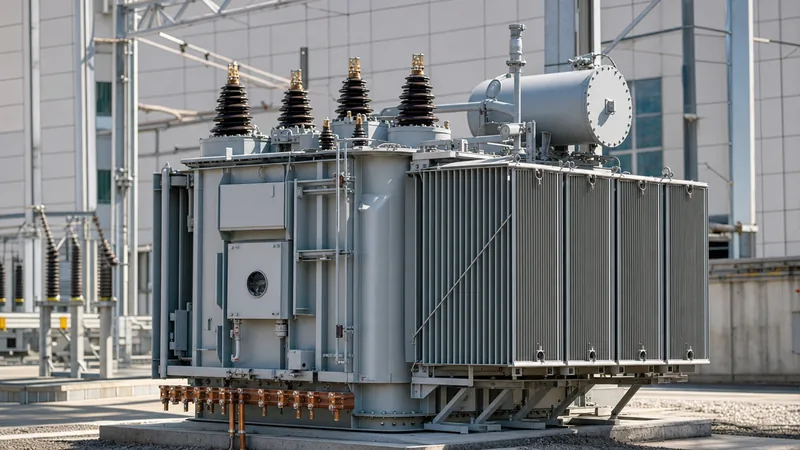
- Substation Transmission and Distribution: Main step-down transformers interface bulk regional transmission networks with municipal sub-transmission grids, maintaining continuous operation under varied outdoor environmental conditions.
- Industrial Distribution: Facilities convert medium-voltage feeds (10 kV to 35 kV) down to 400 V / 230 V using indoor cast-resin equipment. Sizing considerations for these indoor facilities are covered in our comprehensive Dry Type Transformer Guide.
- Rectifier and Converter Transformers: Configured with phase-shifting secondary windings (such as delta-wye dual secondaries providing 12-pulse or 24-pulse rectification) to cancel harmonic distortion in variable frequency drives (VFDs) and electrochemical smelters.
- Instrument Transformers: Potential transformers (PTs) and current transformers (CTs) step down high operational parameters to standardized metering values (such as 110 V and 1 A or 5 A) for protection relays and SCADA telemetry.
Worked Calculation: Transmission Efficiency and I²R Loss Reduction
To demonstrate the primary engineering purpose of stepping up potential differences, consider the transmission of 10 MVA active power over a three-phase line having a total loop resistance of 2.5 ohms per phase at unity power factor.
Scenario A: Transmission at 11 kV (Distribution Level)
- Phase-to-phase voltage (V): 11,000 V
- Line current (I): S / (√3 × V) = 10,000,000 / (1.732 × 11,000) = 524.86 A
- Total Conductor I²R Loss (3 phases): 3 × I² × R = 3 × (524.86)² × 2.5 = 2,066,134 W (2.07 MW)
- Line Transmission Efficiency: (10 MW - 2.07 MW) / 10 MW = 79.3%
Scenario B: Transmission at 132 kV (High-Voltage Transmission Level)
- Phase-to-phase voltage (V): 132,000 V
- Line current (I): S / (√3 × V) = 10,000,000 / (1.732 × 132,000) = 43.74 A
- Total Conductor I²R Loss (3 phases): 3 × I² × R = 3 × (43.74)² × 2.5 = 14,349 W (14.35 kW)
- Line Transmission Efficiency: (10 MW - 0.01435 MW) / 10 MW = 99.86%
By stepping up the voltage by a factor of 12, the conductor losses decrease by the square of the current ratio (a factor of 144), reducing electrical losses from 20.7% down to 0.14%. This mathematical reality underlines the primary purpose of transformer hardware in bulk power systems.
Comparison Matrix: Transformer Types Across Industrial Applications
Engineers must match the design typology to operational environments, safety requirements, and maintenance regimens. The following table compares standard transformer construction types based on typical operational criteria.
| Transformer Type | Typical Voltage Range | Cooling Medium | Short-Circuit Strength | Fire Risk Rating | Applicable Standards |
|---|---|---|---|---|---|
| Liquid-Immersed Distribution | 1 kV to 36 kV | Mineral Oil / Synthetic Ester (ONAN/ONAF) | High (liquid dampens mechanical shock) | Class O1 (Mineral) / Class K (Ester) | IEC 60076-2, IEEE C57.12.20 |
| Cast Resin Dry-Type | 1 kV to 36 kV | Air Natural / Air Forced (AN/AF) | Moderate to High (rigid epoxy encasement) | Class F1 (Self-extinguishing) | IEC 60076-11, UL 1561 |
| High-Voltage Power | 66 kV to 220+ kV | Oil Directed / Water Forced (ODAF/ODWF) | Very High (reinforced core clamps) | Class O1 (Requires fire suppression) | IEC 60076-5, IEEE C57.12.10 |
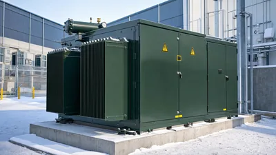
| Pad-Mounted Distribution | 4.16 kV to 34.5 kV | Natural Ester / Mineral Oil (KNAN/ONAN) | High (tamper-proof compartment) | Enhanced fire safety ratings available | IEEE C57.12.34, CSA C227.4 |
Factory Testing and Acceptance Checklist
A factory acceptance test (FAT) confirms that a newly manufactured unit fulfills its design purpose and meets contractual efficiency performance standards. For complete validation routines, consult our guide on Power Transformer Testing.
- Winding Resistance Measurement: Validate conductor continuity and verify balanced resistance across all phases and tap positions using a micro-ohmmeter, verifying conformity against baseline design calculations.
- Voltage Ratio and Vector Group Verification: Measure the open-circuit transformation ratio across all tap changer positions to guarantee accurate turns ratios within the ±0.5% tolerance set by IEC 60076-1 clause 9.3.
- Short-Circuit Impedance and Load Loss Testing: Energize the unit at rated frequency with the secondary short-circuited to determine %Z and copper losses at reference temperature (75°C or 85°C).
- No-Load Loss and Excitation Current: Excite the low-voltage winding at rated voltage while the high-voltage winding remains open to measure iron losses and magnetizing current distortion.
- Dielectric Routine Tests: Apply separate source AC withstand voltage and short-duration induced AC overvoltage (ACSD) to verify inter-turn and winding-to-earth insulation integrity.
- Insulation Resistance and Dissipation Factor: Measure insulation resistance (Megger) and dielectric dissipation factor (tan delta) to ensure zero moisture contamination in the solid insulation cellulose. For ongoing maintenance requirements, review our Transformer Maintenance Guide.
Next steps: specifying and sourcing
Accurate specification ensures your transformer meets the thermal, electrical, and physical demands of your installation. When preparing an RFQ, define rated capacity (kVA or MVA), primary and secondary voltages, vector configuration (e.g., Dyn11), basic impulse insulation level (BIL), impedance percentage, and ambient operating limits. For indoor and safety-critical environments, review our dry-type transformer solutions, or explore oil-immersed transformer and power transformer options for outdoor distribution and sub-transmission networks. Submit your complete single-line diagrams and tender specifications to our application engineers via our quote request page for a competitive, fully compliant engineering proposal.
Frequently asked questions
what is the function of transformer
The function of a transformer is to alter alternating current (AC) voltage and current levels between circuits via electromagnetic induction without changing frequency. It allows power generated at low or medium voltages to be stepped up for long-distance transmission and stepped down for safe consumer usage.
Why cannot transformers operate on direct current (DC)?
Transformers require a continuously changing magnetic flux to induce voltage in the secondary winding, as dictated by Faraday's law. Because steady direct current produces a static magnetic field, no secondary EMF is generated, and the low DC winding resistance will cause destructive overcurrent.
What is the difference between a step-up and step-down transformer?
A step-up transformer features more secondary turns than primary turns, yielding an output voltage higher than the input voltage. A step-down transformer has fewer secondary turns than primary turns, resulting in a lower output voltage suited for end-user equipment.
What causes power losses in an electrical transformer?
Transformer losses comprise no-load losses and load losses. No-load losses occur continuously in the core due to magnetic hysteresis and eddy currents, while load losses result from ohmic resistance (I²R) in the conductor windings and stray eddy currents in structural clamps.
What is the importance of transformer impedance (%Z)?
Transformer impedance determines the total voltage drop under full load and limits the maximum prospective short-circuit current during a fault. Sizing %Z correctly ensures downstream switchgear can interrupt fault currents without exceeding its mechanical and thermal ratings.
Tags: purpose of transformer what is the function of transformer uses of transformer power transformer transformer engineering