Key takeaways
- A swbd electrical unit acts as the primary low-voltage distribution centre, receiving power from step-down transformers or generators and routing it across downstream circuits.
- Switchboard design requires calculating prospective short-circuit withstand ratings (Icw) and thermal limits compliant with IEC 61439-2 clause 8.2 and UL 891.
- Internal forms of separation ranging from Form 1 to Form 4b determine operator protection and service continuity during maintenance on live busbar assemblies.
- In packaged and box-type substations, a low voltage switch board interfaces directly with transformer LV bushings through close-coupled bus ducts or flexible copper droppers.
- Comprehensive factory acceptance testing includes dielectric voltage withstand, contact resistance verification, and secondary injection checks before site commissioning.
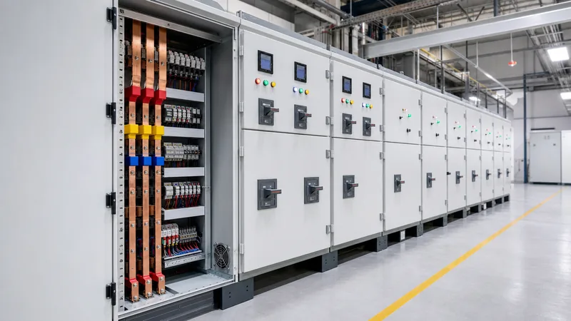
Quick answer: In electrical engineering drawings and single-line diagrams, "SWBD" is the standard notation for switchboard. A swbd electrical assembly is a free-standing low-voltage power distribution enclosure containing horizontal and vertical busbars, circuit breakers, metering devices, and protection relays that distributes bulk electrical energy to sub-panels and heavy mechanical loads.
Industrial facilities, commercial complexes, and modular substations rely on the swbd electrical panel to maintain system reliability, clear downstream overcurrents, and safeguard personnel. Whether engineered as a service-entrance main switchboard or configured as a secondary distribution switchboard, these systems must handle high prospective short-circuit currents while maintaining thermal equilibrium under continuous full-load operating conditions. Selecting and configuring an electrical switchboard demands strict adherence to international performance standards such as IEC 61439-2, UL 891, and NFPA 70 (NEC Article 408).
What Is a SWBD Electrical Assembly?
A swbd electrical enclosure represents the core power distribution hub in a low-voltage electrical installation, operating up to 1000 V AC or 1500 V DC. On engineering schematics, engineering firms label this apparatus as "SWBD" to differentiate dead-front switchboard assemblies from wall-mounted panelboards ("PNL") and motor control centres ("MCC").
Unlike light-duty distribution boards, an industrial switchboard accommodates nominal current ratings from 800 A up to 6300 A. It accepts incoming feeders directly from secondary windings of oil-immersed or dry-type transformers, standby diesel generator sets, or uninterruptible power supply (UPS) banks. The assembly houses high-capacity Air Circuit Breakers (ACBs) or Moulded Case Circuit Breakers (MCCBs), copper or aluminium busbar networks, current transformers (CTs), multifunction power meters, and protective relays. When specifying these systems, consulting engineers must evaluate whether a site requires a draw-out or fixed-pattern main electrical switchboard based on desired operational downtime thresholds during maintenance.
SWBD Electrical Architecture: Main vs Distribution Configurations
Switchboard architecture categorises assemblies into main switchboards and distribution switchboards depending on their position in the network topology. A main switch board is installed at the point of common coupling (PCC) or immediately downstream of substation step-down transformers to serve as the service entrance.
Service-entrance equipment typically incorporates utility metering compartments, a main incoming breaker with earth fault protection, ground-fault sensing, and automatic transfer switches (ATS) to toggle between utility and auxiliary generation feeds. Conversely, a downstream commercial switchboard or distribution tier steps down branch feeders to supply air handling units, elevators, data servers, or sub-distribution panels. For complete low-voltage architecture rules, engineers frequently align design criteria with our comprehensive IEC 61439 Low-Voltage Switchgear Engineering Guide.
While a domestic or house electrical switchboard operates at single-phase 230 V or split-phase 120/240 V with short-circuit levels rarely exceeding 6 kA to 10 kA, a three-phase industrial switchboard operates at 400 V, 480 V, or 690 V and must withstand severe dynamic electrodynamic forces produced by prospective faults exceeding 50 kA or 100 kA.
Switchboard Design Calculations: Busbar Sizing and Fault Rating
Switchboard design relies on rigorous busbar cross-section sizing and short-time withstand current (Icw) validation to prevent conductor melting and mechanical failure. Busbar continuous current carrying capacity is determined by temperature rise limits defined in IEC 61439-1 clause 9.2, which limits busbar surface temperature rises to 70 K above an ambient temperature of 35 °C.
Consider an industrial installation fed by a 2000 kVA, 11 kV to 415 V transformer with a 6% impedance ($Z\% = 6.0$). We calculate the full-load rated current ($I_n$) and prospective symmetrical short-circuit current ($I_{sc}$) at the low voltage switch board terminals:
$$I_n = \frac{S}{\sqrt{3} \times V} = \frac{2,000,000\text{ VA}}{\sqrt{3} \times 415\text{ V}} = 2782.4\text{ A}$$
$$I_{sc} = \frac{I_n}{Z\%} = \frac{2782.4\text{ A}}{0.06} = 46,373\text{ A} \approx 46.4\text{ kA}$$
To withstand this prospective fault for a duration of $t = 1.0\text{ s}$, the minimum cross-sectional area of the main copper horizontal busbar ($S_{cu}$) is calculated using the adiabatic thermal equation from IEC 60364-5-54:
$$S_{cu} = \frac{I_{sc} \times \sqrt{t}}{k}$$
Where $k = 176\text{ A}\cdot\text{s}^{1/2}/\text{mm}^2$ for bare copper conductors with an initial operating temperature of 75 °C and a final transient fault temperature of 200 °C:
$$S_{cu} = \frac{46,373\text{ A} \times \sqrt{1.0\text{ s}}}{176} = 263.5\text{ mm}^2$$
While $263.5\text{ mm}^2$ satisfies short-time thermal rupture requirements, continuous thermal current loading for 3200 A nominal service governs the operational sizing. Applying an empirical design current density of $1.5\text{ A/mm}^2$ for natural convection inside a ventilated IP42 enclosure, the required operational copper area is $3200 / 1.5 = 2133\text{ mm}^2$. The engineering team therefore selects two flat copper bars per phase, each sized at $100\text{ mm} \times 10\text{ mm}$ ($2000\text{ mm}^2$ total per phase), arranged with ventilated spacers to manage electromagnetic skin effect and proximity losses.
Internal Separation Forms in Switchboard Systems
Internal separation partitions a swbd electrical enclosure into segregated compartments to protect operators against accidental contact with live components and contain internal flashovers. IEC 61439-2 clause 8.101 outlines standard configurations from Form 1 through Form 4b.
Specifying the proper separation form balances installation capital costs against plant availability requirements during routine servicing. When specifying high-risk industrial plants, operators also review arc flash safety boundaries to establish proper personal protective equipment (PPE) requirements alongside physical partitioning.
| Form Configuration | Busbars Separated from Functional Units? | Functional Units Separated from Each Other? | Terminals Separated from Busbars? | Terminals Separated from Functional Units? | Typical Application |
|---|---|---|---|---|---|
| Form 1 | No | No | No | No | Basic sub-distribution, low criticality |
| Form 2b | Yes | No | Yes | No | Commercial switchboard installations |
| Form 3b | Yes | Yes | Yes | No | Industrial plants, continuous process |
| Form 4a | Yes | Yes | Yes (in same compartment) | Yes | Power generation, mining switchrooms |
| Form 4b | Yes | Yes | Yes (in dedicated compartment) | Yes | Tier 3/4 data centres, offshore platforms |
Integrating SWBD Systems with Packaged and Unit Substations
In modern industrial and utility layouts, the main electrical switchboard is integrated directly into a compact or containerised substation structure to eliminate long secondary cable runs. Close coupling lowers line-drop voltage losses and limits available fault duration.
When installed within modular housings, as detailed in our unit substation engineering guide, the switchboard is mechanically bolted to the transformer flange via a transition throat or flexible copper busbar connections. These bus links accommodate structural expansion and isolate the distribution switchboard from transformer acoustic vibrations. Designers must guarantee sufficient clearance in the switchroom aisle—at least 1.0 m to 1.2 m according to NFPA 70 Article 110.26—to allow full withdrawal of draw-out circuit breaker cradles without obstructing personnel escape paths. For sites requiring combined medium- and low-voltage switchrooms, coordinate layouts using principles from our medium- and low-voltage electrical switchgear engineering resources.
Factory Acceptance Testing and Commissioning Checklist
A structured testing procedure confirms that a newly manufactured swbd electrical installation matches design specifications and safety standards before on-site energisation. Factory Acceptance Testing (FAT) and Site Acceptance Testing (SAT) must adhere to IEC 61439-1 verification protocols.
- Mechanical and Dimensional Inspection: Verify enclosure structural integrity, paint film thickness (minimum 60 to 80 microns for polyester powder coatings), bolt torque markings across busbar joints, and ingress protection seals (IP31 to IP54 per project specification).
- Dielectric and Insulation Testing: Apply an insulation resistance test at 1000 V DC between phases, and between phases and ground; measured resistance must exceed 100 MΩ. Perform power-frequency dielectric withstand testing at $2U_i + 1000\text{ V}$ (minimum 2200 V AC for 1 minute on a 690 V system) per IEC 61439-1 Table 8.
- Contact Resistance Measurement: Measure micro-ohm resistance across all primary breaker poles and bolted busbar splices using a calibrated digital low-resistance ohmmeter (DLRO); joints must not exceed 20 to 30 micro-ohms depending on busbar cross-section.
- Secondary Injection and Protection Relay Tripping: Perform secondary current injection into electronic trip units (LSIG functions: Long-time, Short-time, Instantaneous, Ground fault) to verify trip curves match selective coordination studies.
- Interlock and Functional Scheme Verification: Test key interlocks (Castell keys), mechanical door interlocks, automatic throw-over logic, and auxiliary signalling contacts for remote Supervisory Control and Data Acquisition (SCADA) networks.
Next steps: specifying and sourcing
When specifying a project-specific switchboard assembly, project engineers should prepare a single-line diagram (SLD), prospective short-circuit fault levels, required form of separation, ambient operating conditions, and ingress protection (IP) ratings. Reviewing your project requirements with an established manufacturing partner ensures compliance with international testing frameworks while optimising enclosure dimensions for substation footprints. Explore our robust range of HV & LV switchgear solutions and skid-mounted prefabricated transformer substations. For project tenders, cost estimations, and bespoke switchboard layouts, visit our quotation inquiry page or connect directly with our application engineers via the contact page.
Frequently asked questions
What does SWBD mean in electrical engineering?
In electrical engineering documentation, SWBD is the standard abbreviation for a switchboard. It denotes a free-standing low-voltage enclosure housing busbars, overcurrent protective devices, and metering equipment that distributes power to multiple sub-circuits.
What is the difference between a switchboard and a switchgear?
The primary difference lies in voltage class, internal construction, and operational standards. Switchboards are dead-front assemblies operating up to 1000 V under standards like UL 891 or IEC 61439, whereas switchgear (UL 1558 or IEC 62271) features fully compartmentalised metal-enclosed construction with higher short-time withstand capabilities, often handling medium-voltage systems.
What is the standard busbar temperature rise in a switchboard?
Under IEC 61439-1 clause 9.2, bare copper busbar connections are permitted a maximum steady-state temperature rise of 70 K above a reference ambient temperature of 35 °C. Under UL 891, the maximum permitted temperature rise at bus connections is 65 °C above a 40 °C ambient.
What form of internal separation is required for industrial switchboards?
Industrial plants typically mandate Form 3b, Form 4a, or Form 4b separation under IEC 61439-2. These configurations isolate the main busbars from functional breaker units and segregate outgoing cable terminals, permitting technicians to work safely on disconnected circuits while the main busbar remains energised.
How often should an electrical switchboard be maintained?
Industrial switchboards require formal visual and thermal inspections every 6 to 12 months, accompanied by annual infrared thermography to identify loose connections. Comprehensive mechanical servicing, contact resistance testing, and breaker lubrication should occur every 3 to 5 years depending on environmental dust and operating duty cycles.
Tags: swbd electrical electrical switchboard main switchboard switchboard design industrial switchboard low voltage switch board


