Key takeaways
- A cast resin transformer encapsulates high-voltage and low-voltage copper or aluminium windings in solid epoxy resin under vacuum, eliminating combustible dielectric fluids.
- Under IEC 60076-11, an E3 C2 F1 rating certifies the unit for severe condensation and pollution (E3), ambient temperatures down to -25°C (C2), and self-extinguishing fire behaviour (F1).
- Cast resin units require partial discharge levels below 10 pC at 1.3 times rated phase-to-ground voltage to guarantee long-term dielectric integrity.
- Thermal protection depends on embedded PT100 resistance temperature detectors or PTC thermistors placed directly between phase windings and tied to a digital monitoring controller.
- Evaluating cast resin transformers manufacturers requires auditing vacuum casting chamber pressures (below 5 mbar) and verifying certified type test reports from independent testing bodies.
Quick answer: A cast resin transformer is a dry-type distribution transformer whose primary and secondary coils are cast in solid epoxy resin under vacuum to prevent fire propagation, eliminate oil leakage, and block environmental moisture ingress. Operating safely inside commercial complexes, industrial plants, and underground substations, it handles voltages up to 36 kV with ratings commonly spanning 50 kVA to 25,000 kVA.
As urban density increases and environmental regulations tighten, specifying power distribution apparatus requires balancing operational reliability with strict fire-safety mandates. Unlike conventional mineral-oil equipment, a dry-type transformer cast resin installation removes flammable liquid inventories from occupied buildings and sensitive industrial infrastructure. For engineers consulting our broader dry-type transformer guide, understanding the core mechanical and dielectric nuances of cast coil assemblies ensures long-term operational resilience without excessive lifecycle maintenance costs.
What Is a Dry Type Transformer Cast Resin Design?
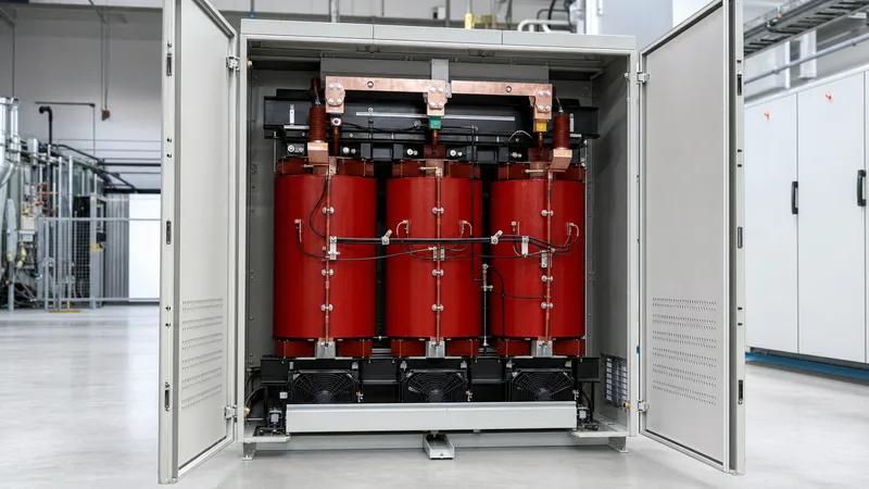
A dry type transformer cast resin design encloses electrical windings inside an inert, fire-retardant composite composed of epoxy resin, curing agents, and mineral fillers such as quartz powder or aluminium trihydrate.
During fabrication, the high-voltage (HV) winding—typically wound from magnet wire or insulated foil—is positioned within precision steel moulds. The assembly enters a vacuum casting chamber where the pressure is drawn down below 5 mbar (0.5 kPa). Formulated liquid epoxy resin is injected under vacuum, completely penetrating every interstitial void between turns before being cured under a tightly regulated temperature profile inside an industrial oven. This process yields a monolithic solid with exceptional mechanical strength against electrodynamic short-circuit forces.
The low-voltage (LV) winding can be executed as a vacuum-impregnated structure or cast similarly in resin using continuous copper or aluminium sheet conductors. Because the resin forms an airtight, moisture-impermeable barrier, the internal conductive elements remain shielded from airborne particulates, industrial chemical vapours, and humid condensation. The resulting dielectric barrier delivers basic insulation level (BIL) ratings up to 170 kV peak for 36 kV class systems, compliant with IEC 60076-11 and IEEE C57.12.01 standards.
IEC 60076-11 Environmental, Climatic, and Fire Classes: E3 C2 F1 Transformers
Standard IEC 60076-11 establishes precise classification codes that define how a dry-type transformer performs under environmental pollution, extreme cold, and direct flame exposure.
Procurement engineers frequently specify e3 c2 f1 transformers for demanding projects such as offshore wind platforms, subterranean rail networks, and heavy chemical processing facilities. Understanding each class designation prevents premature insulation degradation and ensures compliance with building codes:
- Environmental Classes (E0 to E4): Class E0 indicates clean indoor installations with no condensation. Class E1 tolerates occasional condensation and limited pollution. Class E2 accommodates frequent condensation or severe pollution. The rigorous E3 rating certifies the unit to withstand heavy condensation, salt-mist spray, and conductive pollution levels exceeding 3.5 mS/m.
- Climatic Classes (C1 to C4): Class C1 permits transport and storage down to -25°C with operation down to -5°C. Class C2 qualifies the unit to operate reliably, energise, and handle rated load cycles at ambient temperatures as low as -25°C without cracking the cured epoxy blocks.
- Fire Behaviour Classes (F0 to F2): Class F0 indicates no special fire risk limits. Class F1 establishes that the transformer is self-extinguishing within specified timeframes upon ignition removal, produces negligible toxic emissions, emits minimal optical smoke, and contributes minimal calorific energy to an external blaze.
By enforcing an E3 C2 F1 specification, project owners eliminate the need for expensive deluge fire-suppression systems or blast-containment vault walls mandated for liquid-filled assets.
Technical Comparison: Cast Resin vs VPI vs Oil-Immersed Transformers
Selecting the optimal transformer topology involves evaluating dielectric performance, installation constraints, total cost of ownership, and maintenance intervals across competing technologies.
The following engineering data contrasts cast resin transformers with Vacuum Pressure Impregnated (VPI) units and standard mineral oil-immersed distribution units:
| Engineering Parameter | Cast Resin (CR) | VPI Dry-Type | Mineral Oil-Immersed |
|---|---|---|---|
| Fire Safety Classification | IEC F1 (Self-extinguishing) | IEC F0 or F1 (Resin reliant) | Combustible (Class O1 / K1 fluid) |
| Dielectric Fluid Containment | None required | None required | Catchment bund required |
| Partial Discharge Standard | < 10 pC at 1.3 Um | Not strictly governed (> 50 pC) | < 5 pC at 1.3 Um |
| Moisture & Dust Ingress | High resistance (sealed coils) | Moderate (porous surfaces) | Immune (hermetically sealed tank) |
| Short-Circuit Mechanical Rigidity | Superior (monolithic cast) | Moderate (varnish bonded) | High (liquid damped) |
| Overload Capacity (Forced Air) | Up to +40% with AF fans | Up to +33% with AF fans | Limited by fluid thermal inertia |
| Maintenance Requirements | Visual inspection & vacuuming | Frequent cleaning & baking | DGA, oil dielectric testing |
While cast resin units carry a higher initial capital expenditure than VPI or distribution oil units, they eliminate auxiliary civil expenses such as fire catchment sumps, oil-water separators, and automated nitrogen-injection fire-fighting equipment.
How to Size and Select a Cast Resin Transformer
Sizing a cast resin unit correctly requires balancing actual apparent load profiles, k-factor harmonics, ambient temperatures, and enclosure ventilation limits.
- Calculate design kVA: Determine the total connected load, factoring in future growth margins and diversified duty cycles using our transformer sizing calculator guide. Add a 15% to 20% margin for continuous baseload security.
- Account for harmonic heating (K-Factor): Non-linear power electronics such as variable frequency drives (VFDs) and un-interruptible power supplies (UPS) induce eddy current losses in core and coils. Specify K-4, K-13, or K-20 ratings to prevent hot-spot degradation within the solid resin.
- Determine insulation class and temperature rise: Industrial cast resin units standardise on Class F (155°C insulation, 100 K rise limit) or Class H (180°C insulation, 125 K rise limit) systems operating at a nominal 40°C maximum ambient. Selecting a Class H insulation system while running it at Class F temperature rise provides thermal endurance against prolonged overloading.
- Define enclosure ingress protection (IP Rating): Standard indoor units operate inside IP20 or IP21 enclosures with louvred natural air (AN) cooling. For dusty industrial plant rooms, specify IP31 or IP33 enclosures equipped with washable air filters, or step up to forced-air (AF) cooling packages to bolster peak capacity during summer extremes.
- Specify impedance voltage (%Z): Standard values range from 4.0% for units under 630 kVA up to 6.0% or 8.0% for units above 1,600 kVA. Matching %Z is vital when paralleling multiple transformers on a common low-voltage busbar.
Winding Protection and Temperature Monitoring
Thermal overload is the primary failure mechanism in cast resin insulation, requiring dedicated sensor integration directly into the transformer coils.
Because epoxy resin exhibits lower thermal conductivity than dielectric oil, internal hot spots form rapidly under unbalanced loading or harmonic saturation. Manufacturers embed three-wire PT100 resistance temperature detectors (RTDs) or Positive Temperature Coefficient (PTC) thermistors deep within the low-voltage winding layers of each phase. A dedicated digital temperature control unit (TCU) continuously reads these three thermal channels along with core temperature probes.
The controller executes an automated protection matrix:
- Stage 1 (Cooling Fan Activation): Energises forced-air blowers when winding temperatures breach 100°C to 110°C (Class F rating).
- Stage 2 (Thermal Alarm): Transmits an alert contact to the building management system (BMS) or SCADA network via a standard serial communication interface when temperatures reach 130°C.
- Stage 3 (Trip Command): Sends an instantaneous trip signal to the upstream medium-voltage circuit breaker if winding temperatures reach 150°C.
For coordinated substation schemes, see our detailed review of trip curves in the transformer protection engineering guide.
Factory Testing and Partial Discharge Verification
Factory acceptance testing confirms that a cast resin transformer is free from microscopic voids, micro-fissures, and assembly defects that compromise service life.
The partial discharge (PD) test is the critical quality benchmark defined in IEC 60076-11 Clause 14.3. During this test, a high-voltage stress is applied up to 1.8 times rated phase-to-ground voltage (Um/√3) for pre-stressing, then reduced to 1.3 times Um/√3. To pass, the measured partial discharge must remain strictly below 10 picocoulombs (pC), with elite manufacturing standards demanding values under 5 pC. Sustained internal discharges above 20 pC steadily erode epoxy insulation through electrical treeing, eventually causing catastrophic phase-to-ground flashover.
Standard routine factory tests include:
- Measurement of winding resistance on all taps.
- Measurement of voltage ratio and phase displacement vector group verification.
- Short-circuit impedance and load loss measurement at reference temperature (75°C or 115°C).
- No-load loss and no-load current measurement at rated frequency and voltage.
- Separate-source AC withstand voltage test (power frequency dielectric test).
- Induced overvoltage withstand test at double rated voltage and double frequency.
Engineers can reference the step-by-step test methodologies detailed in our guide on how to test a transformer.
How to Evaluate Cast Resin Transformers Manufacturers
Auditing cast resin transformers manufacturers requires verifying their automated resin mixing plant, vacuum casting controls, and testing credentials.
When qualifying potential vendors for commercial or utility projects, engineers should investigate five foundational operational capabilities:
- Resin Degassing and Proportioning Systems: The factory must employ automated, closed-loop batching equipment that degasses pure epoxy resin and filler components separately under dynamic vacuum prior to static mixing. Manual mixing introduces atmospheric air bubbles that cause fatal partial discharge failures.
- Mould Preheating and Curing Autoclaves: Uniform thermal control during mould preheating (typically 80°C to 100°C) and progressive stepped curing (up to 140°C) prevents differential mechanical shrinkage and residual mechanical stress across the winding interfaces.
- Independent Testing Laboratory Accreditations: Demand comprehensive type test reports from internationally recognised test laboratories (such as KEMA, CESI, or equivalent STL members) proving compliance with short-circuit withstand tests and full E3 C2 F1 qualification.
- Core Steel Processing: Verify that the vendor uses laser-scribed, high-permeability grain-oriented (HGO) silicon steel cut on automated step-lap slitting lines to suppress no-load losses and acoustic noise levels below standard NEMA limits.
- Raw Material Traceability: Ensure conductors (Grade A copper or EC-grade aluminium) and epoxy resins are sourced from audited Tier-1 chemical and metallurgical suppliers.
Next steps: specifying and sourcing
To source a reliable cast resin transformer tailored to your exact application, prepare a technical request containing rated power (kVA), primary and secondary voltages, BIL levels, vector group (e.g., Dyn11), tap changer configuration (off-circuit or on-load), ambient temperature extremes, and required enclosure IP rating. Explore our dedicated dry-type transformer solutions, integrate them seamlessly with matching HV and LV switchgear lineups, or package your equipment into factory-assembled compact transformer substations. Contact our application engineering team today at our transformer quotation portal to submit your single-line diagram and receive a fully compliant design proposal.
Frequently asked questions
What is the primary advantage of a cast resin transformer?
A cast resin transformer provides exceptional fire safety and zero risk of fluid leaks because its windings are cast in flame-retardant epoxy resin. It eliminates the need for containment pits, simplifies indoor substation architecture, and operates safely in dense commercial environments.
What does an E3 C2 F1 transformer rating mean?
An E3 C2 F1 rating under IEC 60076-11 certifies that the transformer withstands severe condensation and conductive pollution (E3), can be transported, stored, and operated at temperatures down to -25°C without cracking (C2), and exhibits self-extinguishing, low-smoke fire behaviour (F1).
What is an acceptable partial discharge level for cast resin transformers?
An acceptable partial discharge level is strictly less than 10 picocoulombs (pC) when measured at 1.3 times the rated line-to-ground voltage according to IEC 60076-11. Premium manufacturing processes often attain partial discharge levels below 5 pC to guarantee decades of void-free insulation life.
Can cast resin transformers be installed outdoors?
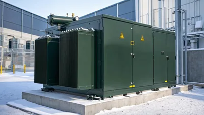
Yes, cast resin transformers can operate outdoors if housed inside a weatherproof, corrosion-resistant enclosure with an appropriate ingress protection rating such as IP44, IP54, or IP55. The enclosure must incorporate sufficient thermal ventilation, anti-condensation space heaters, and filtered air pathways to manage winding heat rejection.
How does forced-air (AF) cooling affect cast resin transformer capacity?
Forced-air cooling using cross-flow blowers increases the continuous output rating of a standard natural-air (AN) cast resin transformer by 25% to 40%. The blowers activate automatically via temperature monitoring relays when base winding temperatures exceed set thresholds during peak load intervals.
How do you maintain a dry type transformer cast resin unit?
Maintenance involves de-energising the unit, performing visual checks for dust buildup, verifying terminal torque tightness, and cleaning the cast resin surfaces using an industrial dry vacuum or dry lint-free cloth. Periodic checks of temperature controller setpoints and RTD resistance continuity ensure trouble-free operation.
Tags: cast resin transformer dry type transformer cast resin e3 c2 f1 transformers cast resin transformers manufacturers distribution transformers