Key takeaways
- Apparent power in kilovolt-amperes represents total electrical capacity combining active real power and reactive inductive power.
- The single-phase formula computes apparent power as current in amperes multiplied by line voltage divided by one thousand.
- The three-phase formula calculates kilovolt-amperes by multiplying line-to-line voltage, line current, and the square root of three, divided by one thousand.
- Solving for voltage requires dividing total volt-amperes by current in single-phase systems or by line current multiplied by 1.732 in three-phase systems.
- Design safety margins under IEC 60076-1 mandate operating steady-state distribution transformers at no more than eighty percent continuous rated capacity.
Quick answer: To figure kVA (kilovolt-amperes) in a three-phase system, multiply line-to-line voltage (V) by line current in amperes (I) and the square root of three (1.732), then divide by 1,000 (kVA = [V × I × 1.732] / 1,000). For a single-phase system, multiply voltage by current and divide by 1,000.
In industrial power distribution, determining the apparent power requirement of a facility is the fundamental first step before sizing switchgear, cables, and transformers. Electrical equipment ratings are expressed in kilovolt-amperes (kVA) rather than kilowatts (kW) because alternating current conductors, magnetic cores, and insulation structures must withstand total current and peak voltage regardless of the system power factor. Understanding how to figure kVA accurately ensures that consulting engineers and engineering, procurement, and construction (EPC) contractors specify distribution assets that avoid thermal tripping while preventing unnecessary capital expenditure on oversized plant.
Whether you are designing a primary substation or auditing plant expansions, using the correct kva calculation formula prevents voltage drop issues and harmonic overheating. For a comprehensive overview of substation network planning, consult our kVA Calculator: Substation & Transformer Sizing Guide.
Understanding the kVA Equation and Apparent Power Basics
The fundamental kva equation expresses apparent power (S) as the vector sum of real working power (P, in kW) and reactive magnetising power (Q, in kVAR). In alternating current circuits containing inductive loads such as induction motors, solenoid valves, and dry-type or oil-immersed transformers, the alternating current waveform lags behind the voltage waveform. This phase displacement creates reactive power that performs no mechanical work yet burdens the distribution network conductors and transformer windings.
The mathematical relationship governing apparent power is defined by the classical power triangle:
- S = √(P² + Q²)
- kVA = kW / Power Factor (cos φ)
- kW = kVA × Power Factor (cos φ)
Electrical equipment manufacturers rate transformers and switchboards in kVA because internal thermal losses—specifically conductor I²R losses governed by IEC 60076-1 clause 5.4—are strictly proportional to current, whilst core excitation losses depend directly on operating voltage. Neither of these physical mechanisms is influenced by load power factor. Consequently, an engineer calculating service capacity must evaluate the total apparent burden rather than simply aggregating nameplate kilowatt ratings.
How to Figure kVA for Single-Phase Electrical Systems
To calculate single-phase kVA, multiply the phase-to-neutral operating voltage by the circuit load current in amperes and divide the result by 1,000. Single-phase arrangements are standard for control power transformers, auxiliary building services, instrumentation skids, and residential tap feeds derived from pole-mounted distribution networks.
The standard single-phase kva calculation formula is expressed as:
kVA = (V × I) / 1,000
Where:
- V = Phase-to-neutral voltage in volts (V)
- I = Full load phase current in amperes (A)
- 1,000 = Conversion factor from volt-amperes (VA) to kilovolt-amperes (kVA)
For example, if an auxiliary heating and lighting distribution panel draws a continuous load of 180 A across a 230 V single-phase utility connection, the required rating is computed as: (230 V × 180 A) / 1,000 = 41.4 kVA. When sizing the upstream feed or isolating unit, engineers apply continuous loading factors per standard electrical codes, typically sizing the source transformer at 125% of continuous load, yielding an optimal commercial selection of 50 kVA.
Three Phase kVA Formula and Calculation Steps
The three phase kva formula calculates total three-phase apparent power by multiplying the nominal line-to-line voltage by the balanced line current and 1.73205 (the square root of 3), divided by 1,000. This calculation forms the basis for sizing medium-voltage (MV) and low-voltage (LV) switchboards, industrial feeders, and package unit substations.
The engineering equation is defined as:
kVA = (V_LL × I_L × √3) / 1,000
Where:
- V_LL = Line-to-line RMS voltage in volts (e.g., 400 V, 480 V, 3,300 V, 11,000 V)
- I_L = Line current in amperes (A)
- √3 ≈ 1.73205 (constant representing the 120-degree phase displacement between vectors)
To master how to compute kva on three-phase networks systematically, follow this practical calculation sequence:
- Measure or specify the nominal phase-to-phase line voltage (V_LL) at the secondary terminals of the supply transformer or main circuit breaker.
- Measure or model the balanced line current (I_L) drawn by all three phases. If phases are slightly unbalanced, calculate the arithmetic mean of the three phases: (I_L1 + I_L2 + I_L3) / 3.
- Multiply line voltage by average line current.
- Multiply that product by 1.73205 to account for three-phase apparent summation.
- Divide the result by 1,000 to convert volt-amperes into kilovolt-amperes.
If you already possess individual phase-to-neutral voltages (V_LN) and line currents, the alternative equivalent formulation is: kVA = 3 × (V_LN × I_L) / 1,000. For cross-checking converted values against feeder amperage limits, review our practical Amps to kVA Conversion Guide.
Converting kVA to Volts and Current Relationships
To convert kVA to volts in an electrical network, divide the apparent power converted into volt-amperes (kVA × 1,000) by the operating current, including the square root of three factor for three-phase installations. In practical electrical engineering, this calculation verifies line voltage drops over extended cable runs or determines required transformer tapping positions under specific load levels.
The formulas for determining kva voltage and converting kva to volts are arranged as follows:
- Single-Phase: Volts (V) = (kVA × 1,000) / I
- Three-Phase: Volts (V_LL) = (kVA × 1,000) / (I_L × √3)
A frequent query from site commissioning engineers involves converting 1000 kva to volts. A rated apparent power value does not determine a fixed voltage by itself; instead, voltage dictates the available rated full-load current across a 1,000 kVA transformer or distribution board. The following engineering reference table demonstrates the inverse relationship between operating voltage and line current across standard international industrial voltages for a 1,000 kVA rating.
| Apparent Power (kVA) | System Type | Nominal Line Voltage (V) | Line Current at 100% Load (A) | Standard Breaker Frame (A) |
|---|---|---|---|---|
| 1,000 | 3-Phase, 50 Hz | 380 V | 1,519.3 A | 1,600 A / 2,000 A |
| 1,000 | 3-Phase, 50 Hz | 400 V | 1,443.4 A | 1,600 A |
| 1,000 | 3-Phase, 60 Hz | 480 V | 1,202.8 A | 1,600 A |
| 1,000 | 3-Phase, 50/60 Hz | 690 V | 836.7 A | 1,000 A |
| 1,000 | 3-Phase, MV | 3,300 V | 174.9 A | 630 A |
| 1,000 | 3-Phase, MV | 11,000 V | 52.5 A | 630 A |
| 1,000 | 3-Phase, MV | 22,000 V | 26.2 A | 630 A |
| 1,000 | 3-Phase, MV | 33,000 V | 17.5 A | 630 A |
As demonstrated, elevating service voltage from 400 V to 11,000 V reduces the continuous conductor current by a factor of 27.5, drastically reducing I²R thermal losses and copper cross-sectional requirements in switchgear busbars and sub-distribution cables.
Worked Sizing Example for an Industrial Unit Substation
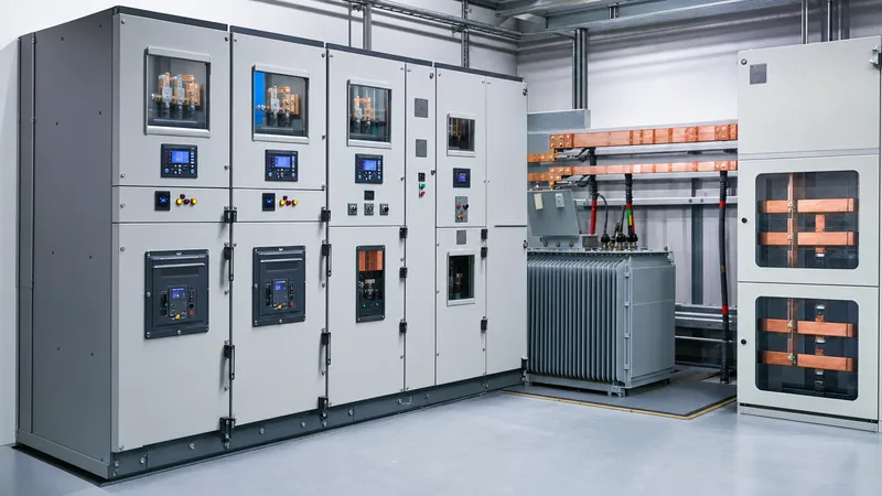
A practical engineering calculation illustrates how to compute kVA from mixed real-power and motor loads to size a complete indoor package substation. Consider an industrial manufacturing facility planning to install an indoor unit substation fed from an 11 kV utility loop to power a 400 V, 50 Hz balance-of-plant distribution board.
The engineering load schedule consists of the following connected equipment:
- HVAC & Process Chillers: 280 kW at 0.82 power factor lagging.
- Air Compressors & Pumping Skids: 190 kW at 0.85 power factor lagging.
- Process Extrusion Machinery: 220 kW at 0.90 power factor lagging.
- Lighting, Controls & Plug Loads: 75 kW at 0.95 power factor lagging.
Step-by-step sizing calculation:
- Calculate individual apparent power and reactive components:
- Chillers: S₁ = 280 / 0.82 = 341.46 kVA; Q₁ = √(341.46² - 280²) = 195.28 kVAR
- Compressors: S₂ = 190 / 0.85 = 223.53 kVA; Q₂ = √(223.53² - 190²) = 117.75 kVAR
- Extrusion: S₃ = 220 / 0.90 = 244.44 kVA; Q₃ = √(244.44² - 220²) = 106.55 kVAR
- Lighting/Aux: S₄ = 75 / 0.95 = 78.95 kVA; Q₄ = √(78.95² - 75²) = 24.65 kVAR
- Sum total active power (P_total) and reactive power (Q_total):
- P_total = 280 + 190 + 220 + 75 = 765.00 kW
- Q_total = 195.28 + 117.75 + 106.55 + 24.65 = 444.23 kVAR
- Compute aggregate uncorrected apparent power (S_total):
- S_total = √(765.00² + 444.23²) = √(585,225 + 197,340) = √782,565 = 884.63 kVA
- Operating system power factor = 765.00 / 884.63 = 0.865 lagging
- Apply diversity factor and future expansion allowance: Assuming an IEEE standard diversity factor of 0.85 across intermittent plant operations and a 20% allowance for future facility expansion:
- Design Operating kVA = (884.63 kVA × 0.85) × 1.20 = 902.32 kVA
- Determine rated secondary line current: Using the three-phase formula: I_L = (902.32 × 1,000) / (400 × 1.73205) = 1,302.38 A.
Based on these precise calculation results, an engineer would specify a standard 1,000 kVA or 1,250 kVA distribution transformer paired with a 1,600 A or 2,000 A incoming low-voltage circuit breaker. For detailed design considerations on packaging these components into integrated enclosures, refer to our Unit Substation Engineering Guide and our detailed Transformer Sizing Calculator Guide.
Practical Application and Sizing Pitfalls in Substation Design
Sizing distribution assets solely on steady-state continuous kVA calculations without accounting for transient dynamics creates operational failures in mission-critical facilities. Industrial power designers must integrate derating factors, transient inrush profiles, and environmental variables into their final equipment capacity selections.
Key engineering pitfalls to avoid during equipment specification include:
- Ignoring Motor Starting Inrush: Large direct-on-line (DOL) squirrel-cage induction motors pull starting currents equal to 600% to 800% of full-load current (IEC 60034-12 Design N). This instantaneous draw causes significant transient voltage dips. If transformer impedance (%Z) is high, secondary bus voltage can plummet below 85%, dropping out sensitive contactors and programmable logic controllers.
- Overlooking Harmonic Derating (K-Factor): Non-linear loads such as variable frequency drives (VFDs) and uninterruptible power supplies (UPS) induce harmonic currents into transformer windings. Triplen harmonics circulate within delta primaries, causing localized eddy current overheating. Engineers must apply IEEE C57.110 derating factors or specify K-4 to K-13 rated dry-type units.
- Ambient Temperature and Altitude Derating: Standard ratings per IEC 60076-2 assume a maximum ambient temperature of 40°C and installation below 1,000 metres above sea level. Operating at 50°C ambient or at 2,200 metres altitude requires derating standard oil-immersed and dry-type units by 8% to 15% due to reduced cooling air density and reduced dielectric insulation strength.
- Continuous 100% Nameplate Loading: Operating transformers continuously at 100% of their base natural-air cooling rating (ONAN or AN) accelerates cellulose insulation ageing. The optimal economic and reliability loading range under cyclic conditions is 65% to 80% of rated nameplate capacity.
Next steps: specifying and sourcing
Accurate load calculations provide the engineering foundation for robust electrical tenders. When preparing your request for quotation (RFQ) or procurement specifications, provide complete single-line diagrams (SLDs), maximum continuous kVA demands, operating ambient extremes, fault level constraints, and winding impedance targets.
Our engineering manufacturing team designs and builds robust, type-tested electrical infrastructure tailored to your exact project parameters. Explore our high-efficiency transformer substations, robust HV/LV switchgear, and liquid-immersed or cast-resin oil-immersed transformers built to strict IEC, IEEE, and ANSI standards. Submit your project requirements via our online quote portal or contact our technical sales specialists directly through our contact page for comprehensive engineering evaluations and certified drawings.
Frequently asked questions
how to figure kva
To figure kVA, multiply operating voltage by full-load current in amperes and divide by 1,000 for single-phase systems (kVA = [V × I] / 1,000). For three-phase systems, multiply line-to-line voltage by line current, multiply by 1.732, and divide by 1,000 (kVA = [V × I × 1.732] / 1,000).
how to compute kva
You compute kVA by establishing your system's line-to-line voltage and operating current, multiplying those figures by 1.732 for three-phase circuits, and dividing the product by 1,000. Alternatively, divide known real active power in kilowatts by the circuit operating power factor (kVA = kW / PF).
What is the kva equation for three-phase systems?
The three-phase kVA equation is kVA = (V_LL × I_L × √3) / 1,000, where V_LL is line-to-line voltage, I_L is line current in amperes, and √3 is approximately 1.732. This equation computes total apparent power regardless of the circuit power factor.
How do you convert 1000 kva to volts?
You convert 1,000 kVA to volts by dividing total volt-amperes (1,000,000 VA) by the line current multiplied by 1.732 in a three-phase system (Volts = 1,000,000 / [I × 1.732]). Voltage depends entirely on the design circuit amperage and cannot be calculated without knowing the operating current.
Why is transformer capacity rated in kVA instead of kW?
Transformers are rated in kVA because core magnetic losses depend on system voltage and winding copper losses depend strictly on current draw. These physical thermal constraints operate independently of the load power factor, requiring thermal sizing against total apparent power (kVA) rather than active power (kW).
Tags: how to figure kva kva equation how to compute kva three phase kva formula kva calculation formula kva to volts


