Key takeaways
- A low voltage panel operates up to 1,000 V AC or 1,500 V DC, serving as the central control point for power distribution, circuit protection, and switching.
- Selecting between an IEC 61439 assembly and a UL 67 480V panelboard depends on prospective fault current, form of internal separation, and regional standards.
- Busbar sizing must account for continuous current carrying capacity, ambient temperature derating, and mechanical bracing against peak short-circuit forces (Ipk).
- Forms of internal separation from Form 1 to Form 4b define the physical barriers between busbars, functional units, and external termination points under IEC 61439-2.
- Factory routine testing requires dielectric verification, insulation resistance testing at 500 V DC minimum, and confirmation of mechanical interlocks before site delivery.
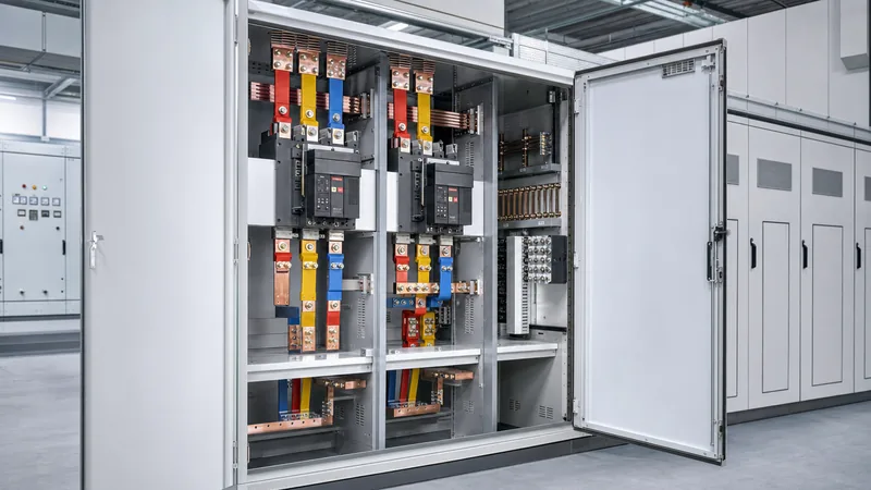
Quick answer: A low voltage panel is an engineered metallic enclosure housing busbars, protective circuit breakers, and auxiliary metering devices designed to receive incoming power below 1,000 V AC and distribute it safely to subsidiary loads. It provides essential short-circuit isolation, thermal overload protection, and circuit switching for commercial buildings, industrial processes, and secondary substations.
Industrial plants and commercial infrastructure rely on low-voltage distribution systems to step down medium-voltage power and manage facility energy safely. Whether configured as a service entrance assembly downstream of a unit substation or as an internal floor-level distribution node, the low voltage panel board isolates network disturbances and prevents catastrophic thermal escalation. Ensuring equipment reliability requires adherence to rigorous testing standards, precise busbar thermal design, and thorough consideration of service conditions, operating duty, and personnel safety.
Low Voltage Panel vs 480V Panelboard: Structural and Standard Classifications
The choice between an international low voltage panel and a North American 480V panelboard is primarily governed by regional design standards, internal segmentation, and continuous current ratings. While both manage low-voltage three-phase distribution, they follow distinctly different engineering frameworks.
Under the international framework defined by the IEC 61439 Low-Voltage Switchgear series, a low-voltage assembly is categorised as a power switchgear and controlgear assembly (PSC-assembly). These panels are modular, floor-standing structures rated up to 6,300 A, designed to withstand high prospective fault currents up to 100 kA or 150 kA for 1 second. Conversely, a typical 480v panelboard designed to UL 67 and NEC Article 408 is traditionally wall-mounted or shallow floor-standing, accommodating main ratings up to 1,200 A with maximum short-circuit ratings rarely exceeding 65 kA.
The structural difference lies in internal isolation and access. A modular low voltage distribution panel incorporates dedicated compartments for horizontal busbars, vertical droppers, functional switching units, and external cabling terminations. In contrast, standard lighting and appliance or power panelboards house overcurrent devices plugged or bolted directly onto a common vertical chassis without compartmentalisation barriers, limiting maintenance flexibility while the board is energised.
Key Engineering Specifications for a Low Voltage Distribution Panel
Specifying a low voltage distribution panel requires calculating three core parameters: rated operational voltage (Ue), rated short-time withstand current (Icw), and enclosure ingress protection (IP/NEMA). These metrics dictate the physical volume, busbar geometry, and ventilation design of the cabinet.
Busbar design is critical for operational longevity. High-conductivity electrolytic copper busbars (minimum 99.9% Cu-ETP under ISO 1337) must be sized not only for continuous load current with derating for ambient temperatures above 35 °C, but also for electromagnetic repulsion forces during fault conditions. Phase conductors must maintain minimum clearance (distance through air) and creepage (distance across insulating surfaces) paths specified in IEC 61439-1 Table 1 and Table 2 based on the rated impulse withstand voltage (Uimp) and pollution degree.
Ingress protection must match the installation environment without causing excessive internal heat accumulation:
- IP31 / IP41: Typical for clean, climate-controlled electrical equipment rooms requiring protection against vertical dripping water and tools larger than 1.0 mm.
- IP54: Standard for dusty or industrial environments, requiring closed-loop forced air exchange or internal air-to-air heat exchangers to prevent particulate ingress.
- NEMA 3R / NEMA 4X: Required for outdoor installations or corrosive coastal environments, utilising heavy-gauge 316L stainless steel or electro-galvanised sheet steel finished with thermoset polyester powder coating.
Worked Calculation: Busbar Sizing and Fault Current Withstand
Determining the busbar cross-section and dynamic short-circuit withstand for a low voltage panel board begins with the supply transformer parameters and fault clearing times. In this worked calculation, an engineer sizes a 480 V low voltage panel supplied by an oil-immersed 1,500 kVA distribution transformer.
First, calculate the transformer rated secondary full-load current (In):
In = S / (√3 × V) = 1,500,000 VA / (1.732 × 480 V) = 1,804.2 A
Applying a continuous loading growth factor of 125% sets the minimum main busbar continuous rating at 2,255 A; thus, a standard nominal busbar rating of 2,500 A is selected.
Next, calculate prospective symmetrical short-circuit current (Isc) assuming an infinite primary grid, with transformer impedance Z% = 5.75%:
Isc = In / (Z% / 100) = 1,804.2 A / 0.0575 = 31,377 A (31.38 kA)
Accounting for low-voltage motor contributions (typically adding 4 times full-load motor currents on the bus), the prospective fault level rises to approximately 38.5 kA. Therefore, the panel busbars and incoming circuit breaker must have a rated short-time withstand current (Icw) of at least 50 kA for 1.0 s.
Under IEC 61439-1, the peak withstand current (Ipk) accounts for the initial DC offset peak factor (n), which for a 50 kA fault (power factor 0.20) equals 2.1:
Ipk = 50 kA × 2.1 = 105 kA peak
To carry 2,500 A with natural convection in a 40 °C ambient enclosure, engineers specify two 100 mm × 10 mm copper laminations per phase. Using the adiabatic thermal equation (IEC 60364-5-54 clause 543.1):
S_min = (Icw × √t) / k
Where k = 176 for bare copper with a initial temperature of 105 °C and final short-circuit limit of 200 °C, and t = 1.0 s:
S_min = (50,000 × 1.0) / 176 = 284 mm²
Because the cross-sectional area of two 100 mm × 10 mm copper bars is 2,000 mm², the thermal capacity far exceeds the minimum 284 mm². The physical sizing is therefore governed by continuous temperature rise limits and the mechanical span between busbar supports to withstand the 105 kA dynamic repulsive force.
Internal Separation Forms in Low Voltage Panel Boards
Internal separation protects operating personnel and limits internal arcing propagation by partitioning the enclosure with metallic or non-metallic barriers. Standardised under IEC 61439-2 clause 8.4, these configurations range from open enclosures (Form 1) to fully compartmentalised assemblies (Form 4b).
Selecting an appropriate separation form balances capital expenditure against maintenance uptime. In critical installations such as data centres, continuous chemical processing, or hospital power plants, Form 4b is mandatory because it permits maintenance technicians to work inside an outgoing cable chamber without de-energising adjacent functional units or the main busbars. Integrating robust internal separation alongside modern arc mitigation technologies reduces personnel hazard, as detailed in our guide on what is arc flash.
| Form of Separation | Busbars Separated from Functional Units? | Functional Units Separated from Each Other? | Terminals Separated from Busbars? | Terminals Separated from Functional Units? |
|---|---|---|---|---|
| Form 1 | No | No | No | No |
| Form 2a | Yes | No | No | No |
| Form 2b | Yes | No | Yes | No |
| Form 3a | Yes | Yes | No | No |
| Form 3b | Yes | Yes | Yes (common) | No |
| Form 4a | Yes | Yes | No | Yes (in same compartment) |
| Form 4b | Yes | Yes | Yes (separate compartments) | Yes (separate compartments) |
For standard light-industrial applications, Form 2b or Form 3b offers a cost-effective compromise. Selecting switchgear with appropriate drawout circuit breakers further enhances isolation, which can be evaluated in our low voltage circuit breaker selection guide.
Factory Testing and Quality Inspection Checklist
A factory-built low voltage panel must undergo stringent design verification and routine testing prior to packaging and sea-freight transport. Engineers and procurement inspectors should witness or verify the following procedural tests on site before sign-off.
- Visual and Dimensional Inspection: Confirm enclosure dimensions, paint thickness (minimum 70–80 µm for powder coating), copper busbar phase markings (L1, L2, L3, N, PE), clearance and creepage distances, and torque markings on all bolted electrical joints.
- Dielectric Withstand Testing: In accordance with IEC 61439-1 clause 10.9, apply a power-frequency test voltage (typically 1,890 V AC for a 690 V rated insulation voltage Ui, or 2,200 V AC for 1,000 V Ui) for 1 second between all live circuits and the interconnected frame.
- Insulation Resistance Verification: Measure insulation resistance using a calibrated megohmmeter at 1,000 V DC before and after the dielectric test. The measured resistance must exceed 100 MΩ across all phases to earth and phase-to-phase.
- Mechanical and Electrical Interlock Checks: Verify the proper operation of door interlocks, circuit breaker racking mechanisms, padlocking provisions, and key interlock exchange systems (e.g., Castell interlocks) between main and tie breakers.
- Secondary Wiring and Functional Testing: Inject current and voltage into auxiliary circuits to verify protection relay pickup thresholds, metering displays, CT polarities, shunt trip activations, and SCADA communications over Modbus or IEC 61850.
Next steps: specifying and sourcing
When preparing an RFQ for a low voltage panel, include your project single-line diagram (SLD), prospective short-circuit level at the incoming terminals, preferred form of internal separation, incoming cable entry direction (top or bottom), and site ambient conditions. Clear boundary definitions streamline engineering approval and shorten factory fabrication cycles. Explore our factory-tested low-voltage switchgear assemblies or complete packaged compact substations for integrated secondary distribution. To submit your engineering schedules or request technical documentation, contact our design team or request a detailed technical quotation.
Frequently asked questions
What is the difference between a switchboard and a low voltage panel?
A switchboard is typically a large, floor-mounted assembly handling main incomers up to 6,300 A with internal compartmentalisation, whereas a low voltage panel often refers to either sub-distribution switchboards or smaller wall-mounted panelboards distributing power to individual branch circuits below 1,200 A.
What voltage ranges are classified under low voltage panels?
Under IEC 61439 and standard electrical codes, low voltage panels operate at voltages up to 1,000 V AC at frequencies up to 1,000 Hz, or up to 1,500 V DC, covering common industrial system voltages such as 400 V, 480 V, and 690 V.
Why is Form 4b internal separation preferred for heavy industry?
Form 4b separation isolates busbars from functional units and provides individual termination compartments for every outgoing circuit cable, ensuring technicians can terminate or service a circuit safely without de-energising adjacent units or exposing themselves to live busbars.
Can a 480V panelboard be installed outdoors?
A 480V panelboard can be installed outdoors if it is housed inside a weather-rated enclosure such as NEMA 3R, NEMA 4X, or minimum IP55, equipped with anti-condensation space heaters and solar radiation shielding.
How is short-circuit withstand rating (Icw) verified in low voltage panels?
Short-circuit withstand is verified through laboratory type-testing in accordance with IEC 61439-1 clause 10.11, subjecting the busbar structure and supports to thermal and dynamic forces under full fault current for a rated duration, typically 1.0 or 3.0 seconds.
Tags: low voltage panel 480v panelboard low voltage panel board low voltage distribution panel switchgear


