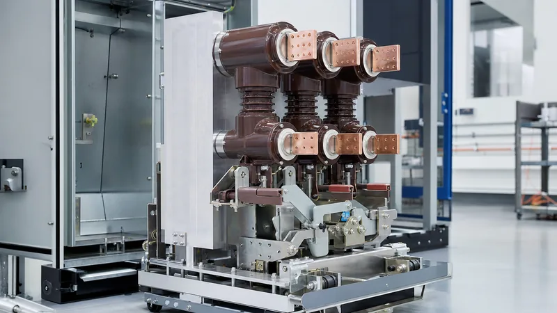
Key takeaways
- Quality circuit breakers must meet IEC 62271-100 Class M2 mechanical endurance (10,000 operations without maintenance) and Class E2 electrical endurance.
- Main circuit contact resistance across vacuum interrupters should remain below 20 to 35 micro-ohms when measured using a calibrated 100 A DC micro-ohmmeter.
- Making capacity requires verification against a peak factor of 2.5 at 50 Hz or 2.6 at 60 Hz relative to the rated short-circuit breaking current.
- Partial discharge levels inside quality medium-voltage circuit breaker poles must not exceed 5 to 10 pC at 1.1 times maximum phase-to-earth operating voltage.
- Routine factory acceptance testing mandates breaker timing, contact travel speed profiling, and a 1-minute power-frequency withstand voltage across open contacts.
Quick answer: Engineering procurement of quality circuit breakers demands strict verification of IEC 62271-100 or IEEE C37.04 endurance classes, vacuum interrupter integrity, low contact resistance, and tested short-circuit interrupting capabilities. A reliable circuit interruption device prevents busbar destruction, eliminates nuisance arc flashes, and maintains power system continuity under severe fault conditions.
Specifying circuit interruption assets for medium-voltage (MV) and low-voltage (LV) systems involves far more than matching continuous operating current and system voltage. In industrial plants, renewable substations, and commercial infrastructure, circuit breakers function as the primary protective barrier against catastrophic thermal and electromagnetic forces. The difference between a standard unit and true quality circuit breakers lies in mechanical tolerances, contact alloy metallurgy, spring-charging mechanism endurance, and stringent factory routine testing. Understanding these technical benchmarks ensures that plant engineers and engineering, procurement, and construction (EPC) professionals select equipment capable of handling high-frequency clearing duties without premature pole degradation or mechanism latch failure.
What Defines Quality Circuit Breakers in Medium-Voltage Applications?
Quality circuit breakers are defined by their verified capability to clear rated symmetrical and asymmetrical short-circuit currents repeatedly without dielectric breakdown or mechanical failure. In medium-voltage distribution systems, vacuum interrupters (VI) and sulphur hexafluoride (SF6) units serve as the primary interrupting media, with vacuum technology dominating up to 38 kV.
International standards establish clear demarcation lines between standard and high-reliability devices. Under IEC 62271-100 clause 6.101, mechanical endurance is categorised into two principal classes:
- Class M1: Standard operational life rated for 2,000 mechanical operations before requiring servicing or overhaul.
- Class M2: High-endurance devices engineered for 10,000 mechanical operations without requiring maintenance of the main contacts or mechanism assemblies.
Electrical endurance is equally vital. Under IEC 62271-100 clause 6.102, a Class E2 breaker is designed for extended electrical life without maintenance of the interrupting parts, clearing short-circuit break operations equal to its full cumulative rated current. For capacitor-bank switching duties, a quality circuit breaker must demonstrate Class C2 compliance, proving very low restrike probability during capacitive current breaking as detailed in our vacuum circuit breaker guide.
Technical Benchmarks: Comparing Standard vs Quality Circuit Breaker Performance
A direct performance gap exists between baseline commercial units and high-specification medium-voltage breakers. When procuring apparatus for mission-critical facilities, such as data centres or heavy manufacturing plants, engineers must evaluate quantifiable parameters against international manufacturing standards.
The following decision table illustrates critical performance benchmarks differentiating baseline equipment from high-specification circuit interruption devices:
| Technical Parameter | Standard Commercial Breaker | High-Specification Quality Circuit Breaker | Reference Standard |
|---|---|---|---|
| Mechanical Endurance | 2,000 operations (Class M1) | 10,000 to 20,000 operations (Class M2/Extended) | IEC 62271-100 cl. 6.101 |
| Electrical Endurance | Class E1 (Basic fault interruptions) | Class E2 (No contact refurbishment needed) | IEC 62271-100 cl. 6.102 |
| Main Contact Resistance | 40 to 65 µΩ | ≤ 20 to 30 µΩ (Copper-Chromium CuCr contacts) | IEC 62271-1 cl. 6.4 |
| Partial Discharge (PD) | ≤ 20 pC at 1.1 Um / √3 | ≤ 5 to 10 pC at 1.1 Um / √3 | IEC 62271-1 cl. 6.2.9 |
| Operating Mechanism | Single-shaft stamped linkages | Modular spring mechanism with hardened alloy cams | IEEE C37.09 Table 1 |
| Rated Operating Sequence | O - 3 min - CO - 3 min - CO | O - 0.3 s - CO - 15 s - CO (Rapid Auto-Reclose) | IEC 62271-100 cl. 4.104 |
| Opening Time | 45 to 65 ms | 30 to 40 ms (Reduces arc flash energy) | IEC 62271-100 cl. 3.7.135 |
Maintaining lower contact resistance directly suppresses internal heat generation inside enclosed switchboards, such as metal clad switchgear, protecting surrounding cast-resin insulators from thermal embrittlement over multi-decade operational cycles.
Factory Acceptance Testing and Verification Protocols
Factory acceptance testing (FAT) for medium-voltage circuit interruption gear confirms that manufactured assemblies adhere directly to certified type-test reports. A comprehensive quality verification programme requires specific routine tests conducted in accordance with IEC 62271-100 clause 7 prior to crating and export dispatch.
- Main Circuit Resistance Measurement: Inject 100 A DC across each pole assembly using a calibrated four-wire micro-ohmmeter. Verify that measured resistance values do not deviate by more than 10% between poles and remain strictly within published factory limits.
- Mechanical Characteristic Timing and Travel Profiling: Mount linear displacement transducers and rotary optical encoders to the operating mechanism. Record opening time, closing time, contact bounce duration (which must remain ≤ 2 ms), contact velocity, and total stroke travel.
- Dielectric Withstand Testing: Apply a dry power-frequency high-voltage potential across open contacts and from phase to earth for 60 seconds (for example, 42 kV RMS for 12 kV equipment, or 70 kV RMS for 24 kV equipment per IEC 60076-3 / IEC 62271-1).
- Vacuum Interrupter Integrity Test: Subject the de-energised vacuum interrupter to an overvoltage withstand test across open contacts to confirm envelope vacuum pressure remains below 10-3 Pa.
- Control and Auxiliary Circuit Verification: Test close and trip coils across operational voltage boundaries, proving proper tripping at 70% to 110% of rated DC supply voltage and closing at 85% to 110% per standard utility specifications.
Field validation procedures for commissioning these assemblies can be cross-referenced within our substation testing guide.
Worked Example: Verifying Short-Circuit and Making Capacity
Sizing and verifying the interrupting and making capabilities of an MV breaker prevents explosive switchgear failure under bolted three-phase fault conditions. Consider an industrial facility connected to an upstream distribution substation with the following electrical characteristics:
- System Nominal Line Voltage ($U_n$): $11\text{ kV}$ (Rated Maximum Voltage $U_r = 12\text{ kV}$)
- Upstream Source Short-Circuit Level ($S_{sc}$): $500\text{ MVA}$
- System Operating Frequency: $50\text{ Hz}$
- Substation Transformer Rating: $20\text{ MVA}$, Impedance voltage $Z_{\%} = 8.0\%$
First, calculate the transformer full-load base current ($I_{FLC}$):
$$I_{FLC} = \frac{S_n}{\sqrt{3} \times U_n} = \frac{20,000\text{ kVA}}{\sqrt{3} \times 11\text{ kV}} = 1,049.7\text{ A}$$
Next, determine the transformer prospective symmetrical short-circuit current ($I_{sc,tx}$):
$$I_{sc,tx} = \frac{I_{FLC}}{Z_{\%} / 100} = \frac{1,049.7}{0.08} = 13,121\text{ A} = 13.12\text{ kA}$$
Calculating the upstream grid contribution ($I_{sc,grid}$):
$$I_{sc,grid} = \frac{500,000\text{ kVA}}{\sqrt{3} \times 11\text{ kV}} = 26,243\text{ A} = 26.24\text{ kA}$$
Combining system impedances results in a total prospective symmetrical fault current ($I_{sc,total}$) at the 11 kV switchboard busbar of approximately $8.75\text{ kA}$ if fed exclusively through the transformer, or up to $25.0\text{ kA}$ under direct busbar fault contingencies. Therefore, an engineer should select a standard breaking current rating ($I_{sc}$) of $25\text{ kA}$ or $31.5\text{ kA}$.
Under IEC 62271-100 clause 4.103, the rated short-circuit making current ($I_{ma}$) must withstand the initial asymmetrical peak current. At 50 Hz, the standard peak factor for an $X/R$ ratio representing typical distribution networks is 2.5:
$$I_{ma} = 2.5 \times I_{sc} = 2.5 \times 31.5\text{ kA} = 78.75\text{ kA (peak)}$$
A sub-standard breaker may claim a 31.5 kA symmetrical rating but incorporate an undersized closing spring that stalls against electromagnetic repulsion forces, failing to latch under this 78.75 kA peak. A verified high-specification unit ensures the dynamic force of its mechanical spring linkage exceeds contact repulsion forces by a minimum safety margin of 20%.
Common Manufacturing Deficiencies and Field Failure Modes
Premature failure of switchgear circuit breakers stems from metallurgical shortcuts, inadequate assembly tolerances, or substandard insulation casting. Understanding these failure mechanisms enables procurement engineers to inspect equipment critically during factory audits.
One frequent mode of failure is vacuum bottle degradation caused by micro-fissures in the ceramic-to-metal braze joints. If residual internal atmospheric pressure exceeds $10^{-2}\text{ Pa}$, the vacuum interrupter cannot sustain its dielectric strength during contact separation, leading to sustained arcing and chamber explosion. Premium manufacturers employ copper-chromium (CuCr) contact discs sintered under ultra-high vacuum conditions to prevent gas liberation over thermal cycling.
Another common mechanical vulnerability lies in the mechanism latch and roller bearings. Low-grade carbon steel latches subjected to continuous spring tension experience surface brinelling and galling. Over 3 to 5 years, this microscopic indentation increases the required trip latch force, causing the shunt trip solenoid to stall and preventing the breaker from opening during an overcurrent event. Quality breakers utilise vacuum-hardened stainless steel or chrome-molybdenum alloys on all primary tripping pawls. For broader switchboard layout criteria, review our guide to MV switchgear engineering.
Procurement Checklist for Switchgear Integration
When preparing a Request for Quotation (RFQ) for high-reliability breakers, project specifications should include mandatory compliance clauses that prevent low-tier vendors from offering inferior commercial models. Use the following specification checklist in technical tender documentation:
- Standards Compliance: Mandatory proof of complete type testing at an accredited STL laboratory (KEMA, CESI, or ASTA) to IEC 62271-100 or IEEE C37.09.
- Endurance Certification: Formal verification of Class M2 mechanical endurance (10,000 operations) and Class E2 electrical endurance without contact replacement.
- Bushing and Pole Construction: Embedded pole design using solid epoxy resin casting rather than open-air assembly, eliminating surface dust accumulation and moisture ingress along the vacuum interrupter shell.
- Operating Mechanism: Front-accessible, modular spring mechanism with manual charging handle, mechanical open/close pushbuttons, and clear mechanical flag indicators for spring charged/discharged and breaker status.
- Interlocking Integrity: Internal mechanical interlocks preventing racking into the connected position when contacts are closed, and preventing manual or electrical closure when the breaker is between defined test and disconnected positions.
- Secondary Disconnect: Robust multi-pin umbilical control wiring plug with silver-plated pins rated for at least 500 rack-in/rack-out cycles.
Next steps: specifying and sourcing
Sourcing quality circuit breakers requires rigorous validation of short-circuit breaking capacity, impulse withstand levels, and factory quality assurance processes. When submitting design packages for technical bids, provide single-line diagrams, short-circuit calculations, continuous ampacity requirements, and secondary control schematics. Explore our primary HV and LV switchgear portfolios or integrate complete switchgear lineups into custom transformer substations. To discuss your project specifications or request an engineering review from our technical design department, submit your inquiry through our quotation request page.
Frequently asked questions
What is the difference between Class M1 and Class M2 circuit breakers?
Class M1 circuit breakers are rated for 2,000 mechanical operations before requiring maintenance, suitable for standard distribution networks. Class M2 breakers are engineered for 10,000 operations without maintenance, intended for industrial processes and installations with frequent daily switching cycles.
How often should contact resistance be tested on medium-voltage breakers?
Contact resistance should be measured during initial commissioning, annually during routine preventive maintenance, and immediately following severe short-circuit interruption events. A resistance increase greater than 20% over baseline factory test records indicates contact wear, oxidation, or improper contact spring pressure.
Why is embedded pole technology superior to assembled pole design?
Embedded poles cast the vacuum interrupter directly into solid polyurethane or epoxy resin, shielding the ceramic shell from dust, moisture, vermin, and mechanical impact. This construction eliminates internal flashovers and maintains dielectric integrity in humid, polluted, or aggressive industrial operating environments.
What causes a vacuum circuit breaker to fail to trip?
Failure to trip typically results from mechanical latch brinelling, dried lubrication on the trip shaft, a burned-out shunt trip coil, or low auxiliary battery bank DC voltage. Proper preventative maintenance and periodic mechanism timing tests identify high mechanical friction before catastrophic failure occurs.
What is the significance of the rated operating sequence O-0.3s-CO-15s-CO?
This sequence defines the rapid auto-reclose duty cycle of the circuit breaker. It proves the device can open during a fault, reclose after 0.3 seconds onto a lingering fault, trip instantly, and perform a final closing-opening operation after 15 seconds without thermal failure.
Tags: quality circuit breakers quality circuit breaker vacuum circuit breaker switchgear MV switchgear IEC 62271-100


