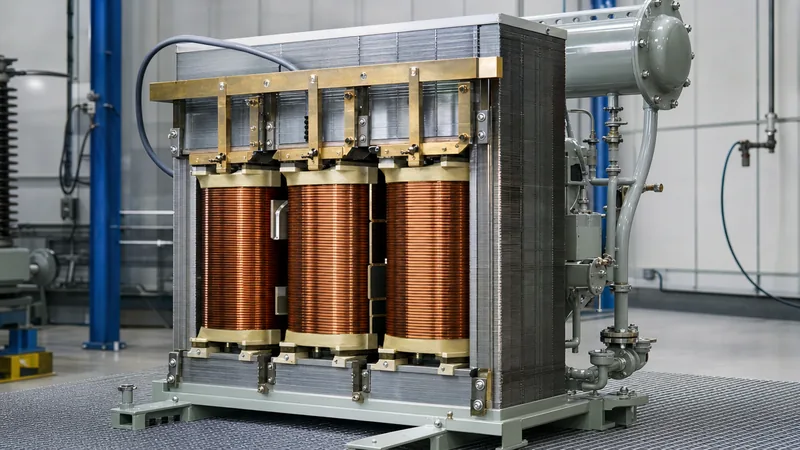
Key takeaways
- Transformers are rated by their capacity in apparent power (volt-amperes, kVA, or MVA) because internal thermal losses depend directly on voltage and current regardless of downstream power factor.
- Core losses (iron losses) are governed by operating voltage and frequency, whereas copper losses (winding losses) are determined by the square of load current (I²R).
- Specifying a transformer in real power (kW) risks severe thermal overloading when supplying inductive or capacitive loads operating at low lagging or leading power factors.
- Standard cooling classes such as ONAN and ONAF alter transformer capacity ratings dynamically by shifting thermal dissipation rates according to IEC 60076-2 limits.
- Accurate substation specification requires applying appropriate harmonic derating (K-factor) and ambient temperature correction factors per IEEE C57.12.00.
Quick answer: In electrical engineering, transformers are rated by their capacity in apparent power, specifically volt-amperes (VA), kilovolt-amperes (kVA), or megavolt-amperes (MVA). This rating is chosen because internal heating and physical limits are dictated by operating voltage and load current, completely independent of the connected load's power factor.
When design engineers and procurement teams review manufacturer nameplates, they frequently observe that transformers are usually rated in units called kVA or MVA rather than active power units like kilowatts (kW) or megawatts (MW). Sizing distribution and substation assets strictly by active power requirements leads to undersized conductors, compromised insulation life, and catastrophic thermal runaway. Understanding the physical mechanisms behind apparent power ratings ensures that your substation plant operates within permissible temperature rises throughout its design lifespan. To evaluate full installation requirements, consult our kVA Calculator: Substation & Transformer Sizing Guide.
Why Transformers Are Rated by Their Capacity in Apparent Power
Transformers transfer electrical energy between voltage levels through electromagnetic induction, and their capacity limits are governed purely by voltage insulation thresholds and winding thermal tolerances. Under IEC 60076-1 clause 4.1, rated power represents the continuous apparent power assigned to a winding under rated voltage and frequency without exceeding specified temperature rises.
Two primary internal loss mechanisms generate heat within any core-and-coil assembly:
- Core (iron) losses: Hysteresis and eddy current losses occur within the magnetic steel laminations. These losses are continuous whenever the primary winding is energised and depend strictly on applied voltage and frequency, irrespective of load current.
- Winding (copper) losses: Resistive losses (I²R) and stray eddy losses occur in primary and secondary conductor windings. These losses depend exclusively on the magnitude of the circulating current passing through the coils.
Because neither core excitation nor resistive conductor heating depends on the phase angle between voltage and current, the load's power factor (cos φ) has zero influence on the internal thermal dissipation of the unit. A transformer handling 1,000 A at 400 V produces the exact same winding temperature rise whether the load operates at 1.0 power factor (unity) or 0.6 power factor (lagging). Sizing the unit in kW would obscure this fundamental current constraint.
Why kW Ratings Fail in Electrical Substation Sizing
Using active power (kW) to size a transformer creates substantial operational risk because active power accounts only for the work-producing component of total power. The relationship between active power (P), apparent power (S), and power factor (PF) is defined as:
S (kVA) = P (kW) / PF
If a facility load demands 800 kW at a 0.8 lagging power factor, the apparent power imposed on the distribution equipment is:
S = 800 kW / 0.8 = 1,000 kVA
If an engineer improperly specified an 800 kW-rated transformer, the unit would draw 1,000 kVA of physical current through its windings. This produces a current overload of 125%, accelerating winding insulation deterioration according to the Arrhenius rate equation. For practical mathematical procedures on deriving system currents, review our guide on how to figure kVA across balanced three-phase systems.
Standard Transformer Capacity Ratings and Cooling Impact
Transformers are manufactured in standardised capacity steps defined by international bodies, with cooling provisions directly modifying the continuous nameplate capacity. IEC 60076-1 and IEEE C57.12.00 Table 5 establish standard kVA increments across medium-voltage and low-voltage networks. Forced-cooling mechanisms alter the apparent power output by improving heat extraction away from the core and winding ducts.
| Cooling Class (IEC / IEEE) | Core & Coil Medium | Circulation Mechanism | Capacity Increase over Base | Typical Application |
|---|---|---|---|---|
| ONAN / OA | Mineral or ester oil | Natural convection oil, natural air | Base rating (100%) | Standard pad-mount & distribution |
| ONAF / FA | Mineral or ester oil | Natural convection oil, forced fan air | +25% to +33% | Unit substations & peak loading |
| OFAF / FOA | Mineral or ester oil | Forced pump oil, forced fan air | +50% to +67% | Large transmission & step-up units |
| AN / AA | Dry-type (vacuum cast resin) | Natural ambient air circulation | Base rating (100%) | Indoor switchrooms & commercial hubs |
| AF / FA | Dry-type (vacuum cast resin) | Forced motor-driven cross-flow fans | +33% to +50% | Data centres & industrial unit substations |
A dual-rated transformer marked ONAN/ONAF 2,000 / 2,500 kVA can continuously sustain 2,000 kVA relying on ambient radiator draft, but engages automated fan stages to dissipate internal losses safely at 2,500 kVA. Detailed operational parameters for packaged indoor installations are discussed in our Unit Substation Engineering Guide.
Worked Engineering Calculation: Sizing by Apparent Power
To demonstrate correct capacity selection, consider a manufacturing plant expanding its distribution network with the following continuous loads connected to a 415 V three-phase, 50 Hz busbar:
- Linear resistive process heaters: 250 kW at 1.0 PF.
- Three-phase induction drive motors: 420 kW at 0.82 PF lagging.
- Switch-mode electronics & lighting: 110 kW at 0.90 PF lagging.
- Design spare capacity: 20% allowance for future expansion.
Calculate the individual apparent power (S) and reactive power (Q) demands using standard trigonometric power triangles:
- Heaters: S₁ = 250 / 1.0 = 250.0 kVA; Q₁ = 0.0 kvar
- Motors: S₂ = 420 / 0.82 = 512.2 kVA; Q₂ = √(512.2² - 420²) = 293.1 kvar
- Electronics: S₃ = 110 / 0.90 = 122.2 kVA; Q₃ = √(122.2² - 110²) = 53.3 kvar
Summing the active and reactive components:
P_total = 250 + 420 + 110 = 780 kW
Q_total = 0.0 + 293.1 + 53.3 = 346.4 kvar
Compute the total operating apparent power (S_total):
S_total = √(P_total² + Q_total²) = √(780² + 346.4²) = √(608,400 + 119,993) = 853.5 kVA
Applying the 20% future growth allowance:
S_required = 853.5 kVA × 1.20 = 1,024.2 kVA
Evaluating standard manufacturer increments (800 kVA, 1,000 kVA, 1,250 kVA, 1,600 kVA), an engineer must select a 1,250 kVA rating. A 1,000 kVA transformer would operate above its thermal design baseline during peak operating periods, violating IEC 60076 temperature rise criteria.
Thermal Limits and Winding Temperature Rise Standards
A transformer's apparent power rating is directly anchored to its maximum allowable thermal envelope. Under continuous rated kVA operation, the internal losses heat the conductors, solid dielectric paper, and cooling fluid until steady-state equilibrium is achieved.
IEC 60076-2 and IEEE C57.12.00 establish explicit temperature rise ceilings above ambient conditions (standardised at 40°C maximum ambient and 30°C annual average ambient):
- Top liquid temperature rise: 60 K (mineral oil with conservator) or 65 K (sealed units).
- Average winding temperature rise: 65 K for standard Class A insulation systems.
- Winding hot-spot temperature rise: 78 K above ambient, limiting the continuous hot-spot operating limit to 98°C at standard ambient or 110°C during maximum ambient peaks.
For dry-type transformers built with Class F (155°C) or Class H (180°C) Nomex insulation, allowable rises are higher (typically 100 K or 125 K rise). Exceeding rated kVA produces temperature escalation that degrades the degree of polymerisation (DP) of cellulose insulation, halving its dielectric lifespan for every 6 K to 8 K sustained above design limits. For comprehensive monitoring strategies, examine our Winding Temperature Guide: Transformer Thermal Limits.
Derating Factors to Review Prior to Equipment Sourcing
Before finalising an equipment purchase order, apparent power capacity must be derated for non-standard operating conditions. Nameplate ratings assume clean sinusoidal currents, sea-level atmospheric pressures, and moderate climates.
Key derating criteria include:
- High altitude installation: At altitudes exceeding 1,000 metres above sea level, lower air density reduces convective heat transfer and dielectric withstand clearance. Dry-type units generally require a 0.5% derating per 100 metres above 1,000 m per IEC 60076-11 clause 11.2.
- High ambient temperature: If the local maximum ambient exceeds 40°C, continuous kVA capacity must be reduced by 1% to 1.5% per degree Celsius above standard baselines.
- Non-linear harmonic loading: Rectifiers, variable frequency drives, and battery energy storage inverters introduce high-frequency harmonic currents. Eddy losses in windings increase proportionally to the square of harmonic order and frequency (I_h² × h²). Specifying engineers must calculate the system K-factor per IEEE C57.110 to select appropriate core and conductor upgrades.
Next Steps: Specifying and Sourcing
When preparing technical bid documents, specifying engineers should provide a comprehensive schedule of requirements including primary and secondary voltages, winding vector groups (such as Dyn11), short-circuit impedance percentage (%Z), ambient temperature extremes, and the calculated continuous apparent power rating in kVA. Explore our pre-engineered transformer substations, robust oil-immersed transformers, and high-efficiency dry-type transformers designed to IEC and IEEE standards. Submit your single-line diagrams and duty profiles directly via our transformer quotation request portal to receive full engineering support and performance data sheets.
Frequently asked questions
Why are transformers rated in kVA instead of kW?
Transformers are rated in kVA because their heating and loss mechanisms depend solely on voltage and current. Iron core losses depend on applied voltage, while copper losses depend on load current magnitude, neither of which is influenced by load power factor.
Can a transformer supply its full rated kVA at low power factor?
Yes, a transformer can supply its full rated kVA at low power factors, but the delivered real work (kW) will be significantly lower. For instance, a 1,000 kVA transformer at 0.5 power factor delivers only 500 kW of useful work while operating at 100% thermal capacity.
What happens if you run a transformer beyond its kVA rating?
Operating above rated kVA increases internal I²R conductor losses, producing excessive winding hot-spot temperatures. Sustained overheating rapidly deteriorates solid dielectric insulation, accelerates oil acidity formation, and can lead to inter-turn short circuits.
What does a dual kVA rating like 1500/2000 kVA mean?
A dual rating indicates two continuous thermal operating stages based on cooling mode. The lower figure represents natural cooling capacity (ONAN or AN), whereas the higher figure denotes maximum capacity achieved with auxiliary cooling fans active (ONAF or AF).
How does harmonic current impact transformer kVA capacity?
Harmonic currents cause elevated eddy current and stray flux losses in windings and structural metal, creating localized hot spots. Under significant non-linear loads, a standard transformer must either be derated or engineered with a specific K-factor rating.
Tags: transformers are rated by their capacity in transformers are usually rated in units called transformer kVA rating apparent power sizing substation design


