Key takeaways
- A 15kV switchgear assembly typically operates at nominal system voltages between 11kV and 13.8kV, requiring a rated lightning impulse withstand voltage (BIL) of 95kV crest under IEEE C37.20.2 or IEC 62271-200.
- Transitioning from 5kV switchgear or 4160v switchgear to 15kV equipment increases busbar phase-to-phase clearance requirements from 89mm (3.5 inches) to 152mm (6.0 inches) for air-insulated configurations.
- True metal-clad switchgear incorporates fully grounded metal barriers between the circuit breaker, main bus, incoming/outgoing cables, and low-voltage control compartments, unlike basic medium voltage metal enclosed switchgear.
- Modern vacuum circuit breakers have completely replaced medium voltage air breakers due to their hermetic arc containment, 30,000-operation mechanical life, and zero maintenance interrupter bottles.
- A standard medium voltage switchgear specification must define symmetrical short-circuit current ratings, internal arc classification (IAC AFLR), and current transformer accuracy classes per IEEE C57.13 or IEC 61869-2.
Quick answer: A 15kV switchgear assembly is an engineered lineup of centralised electrical distribution equipment designed to control, protect, and isolate medium-voltage circuits operating between 11kV and 14.4kV. It combines draw-out vacuum circuit breakers, copper busbars, protective relays, instrument transformers, and grounded metallic compartmentalisation to interrupt fault currents up to 50kA safely.
In industrial plants, utility substations, critical data centres, and renewable generation facilities, the 15kV switchgear functions as the critical power distribution backbone. Specifying this equipment requires an exact understanding of dielectric insulation distances, dynamic short-circuit electrodynamic forces, thermal limits under continuous full-load ampacity, and rigorous safety standards such as IEEE C37.20.2 and IEC 62271-200. Selecting incorrect breaker parameters or enclosure partitions can lead to catastrophic arc-flash events, prolonged plant downtime, or severe equipment damage.
Understanding how 15kV assemblies differ from lower medium-voltage tiers, such as 5kV or 4160V gear, ensures that project engineers design resilient, code-compliant single-line architectures. For a broader overview of medium-voltage architectures, consult our detailed MV switchgear engineering guide.
15kV Switchgear Technical Architecture and Voltage Ratings
A rated 15kV switchgear lineup provides electrical isolation and fault protection for systems operating at standard nominal voltages of 11kV, 12.47kV, 13.2kV, and 13.8kV. Under IEEE C37.20.2 Table 1 and IEC 62271-1 Table 1A, equipment rated at the 15kV class must withstand a maximum design voltage of 15kV (or 17.5kV under specific IEC classifications), with a power-frequency withstand voltage of 36kV RMS (1 minute) and a basic lightning impulse insulation level (BIL) of 95kV peak.
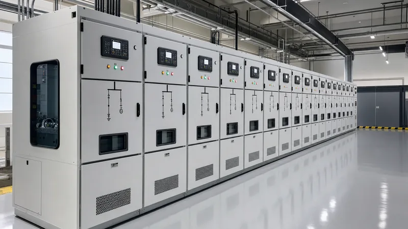
The structural assembly consists of heavy-gauge, galvanised or aluminised steel frames divided into distinct vertical sections called bays or cubicles. Each vertical section is partitioned into four segregated compartments: the circuit breaker cell, the main busbar compartment, the cable termination compartment, and the isolated low-voltage instrument compartment. Internal barriers prevent an arc or thermal runaway event in one compartment from migrating to adjacent bays.
Main horizontal busbars are fabricated from 99.9% electrical-grade E-Cu copper, fully silver-plated or tin-plated at all bolted joints. To prevent phase-to-phase and phase-to-earth flashovers caused by airborne contamination or vermin entry, busbars in 15kV air-insulated gear are shrouded in high-dielectric fluidised-bed epoxy insulation or heat-shrinkable polyolefin tubing capable of withstanding the full 15kV phase-to-ground potential without puncture.
Comparing 15kV Switchgear to 5kV and 4160V Switchgear
Engineers must evaluate dielectric clearances, insulation classes, and component physical footprints when comparing 15kV switchgear to 5kv switchgear and 4160v switchgear. While 4160V systems are widely deployed for large industrial motor drives and primary process distribution, 15kV distribution offers significantly lower line losses ($I^2R$) and smaller cable cross-sections over campus-scale distances.
Dielectric requirements diverge substantially between these voltage classes. A standard 5kV or 4160V lineup requires a basic impulse level (BIL) of 60kV crest and a 1-minute power-frequency withstand of 19kV RMS. In contrast, 15kV equipment demands a 95kV BIL and a 36kV RMS test voltage. This disparity dictates much larger air-strike clearances: minimum phase-to-phase air clearance increases from 89mm (3.5 inches) in 5kV systems to 152mm (6.0 inches) in 15kV systems.
| Engineering Parameter | 5kV Class / 4160V Switchgear | 15kV Class Switchgear | Governing Standard |
|---|---|---|---|
| Maximum Rated Voltage ($V_{\text{max}}$) | 4.76 kV or 5.0 kV | 15.0 kV (ANSI) / 17.5 kV (IEC) | IEEE C37.20.2 / IEC 62271-1 |
| Impulse Withstand (BIL) | 60 kV crest | 95 kV crest | IEEE C37.20.2 Table 1 |
| Power Frequency Withstand (1 min) | 19 kV RMS | 36 kV RMS | IEC 62271-1 clause 6.2 |
| Minimum Air Clearance (Phase-to-Earth) | 76.2 mm (3.0 in) | 139.7 mm (5.5 in) | IEEE C37.20.2 Table 2 |
| Minimum Air Clearance (Phase-to-Phase) | 88.9 mm (3.5 in) | 152.4 mm (6.0 in) | IEEE C37.20.2 Table 2 |
| Standard Continuous Bus Ratings | 1200 A to 3000 A | 1200 A to 4000 A | ANSI/IEEE C37.55 |
| Typical Short-Circuit Interruption | 25 kA to 50 kA | 25 kA to 63 kA | IEC 62271-200 / IEEE C37.04 |
Due to the increased physical clearance, cubicle widths grow from 660mm (26 inches) in 5kV designs to 914mm (36 inches) in 15kV metal-clad configurations, directly impacting substation room layouts. To explore structural details between different constructions, review our guide on metal-clad switchgear engineering.
Metal-Clad vs Medium Voltage Metal Enclosed Switchgear
The choice between metal-clad construction and basic medium voltage metal enclosed switchgear represents a critical trade-off between personnel safety, circuit reliability, and capital expenditure. While both designs house components in grounded sheet metal enclosures, their internal segregation and operational mechanics differ fundamentally under IEEE C37.20.2 and IEEE C37.20.3.
True metal-clad switchgear features complete internal partitioning using grounded 11-gauge (3.0mm) sheet steel to separate the circuit breaker, instrument transformers, main bus, and power cable terminations. It requires draw-out switching devices with self-aligning disconnect mechanisms, automatic grounded safety shutters that shield live stabs when the breaker is racked out, and segregated low-voltage wireways.
Conversely, medium voltage metal enclosed switchgear typically utilizes fixed-mounted circuit switches, load-break interrupters, or non-compartmentalised vacuum breakers. Common barriers are omitted between the bus and cable landing areas, meaning an arc flash in the cable section directly affects the main busbar. Metal-enclosed equipment is common for simple, single-breaker transformer primary protection, whereas critical 15kV plant substations specify metal-clad architecture to allow breaker maintenance without de-energising the entire lineup.
Vacuum Breakers vs Medium Voltage Air Breakers
Historically, legacy 15kV distribution systems relied on medium voltage air breakers that used atmospheric air, magnetic blowout coils, and refractory arc chutes to stretch, cool, and extinguish medium-voltage arcs. These electro-mechanical assemblies were mechanically complex, occupied significant spatial volume, produced violent exhaust gases during fault clearing, and required extensive contact resurfacing after each interruption.
Modern 15kV installations universally adopt vacuum circuit breakers (VCBs). In a vacuum interrupter bottle, the contact separation occurs within an ultra-high vacuum environment sealed at approximately $10^{-7}$ mbar ($10^{-5}$ Pa). Because free electrons have a mean free path far exceeding the contact gap (typically 10mm to 12mm), dielectric recovery occurs almost instantaneously at the first current zero, eliminating open-air thermal plasma discharges.
Vacuum circuit breakers require virtually zero maintenance on the interrupter contacts, deliver a mechanical endurance of 10,000 to 30,000 operations, and reduce the breaker compartment weight by more than 60% compared to legacy air-magnetic units. Detailed electrical operating mechanisms and sizing calculations are examined in our comprehensive vacuum circuit breaker guide.
Step-by-Step Medium Voltage Switchgear Specification and Sizing
Formulating a rigorous medium voltage switchgear specification requires calculating continuous thermal currents, symmetrical short-circuit duties, and transient peak making capabilities based on the upstream transformer and utility grid characteristics. The sizing process follows a rigorous sequence:
- Calculate the nominal full-load continuous operating current ($I_n$) of the main incomer bay based on transformer primary rating.
- Calculate the three-phase bolted prospective symmetrical short-circuit current ($I_{\text{sc}}$) at the 15kV busbar.
- Determine the asymmetrical peak making current ($I_{\text{peak}}$) accounting for system $X/R$ inductive ratios.
- Verify thermal sizing of copper busbars and earthing systems for a defined duration (typically 2 or 3 seconds).
- Select instrument transformer burdens, accuracy classes, and protective relays matching utility interconnect criteria.
Consider a practical engineering calculation for an industrial facility fed by a 15 MVA, 115 kV to 13.8 kV oil-filled step-down transformer having an impedance of $Z_{\%} = 8.0\%$ with an upstream infinite utility source:
$$\text{Full Load Current } I_{\text{FLA}} = \frac{S_{\text{kVA}}}{\sqrt{3} \times V_{\text{LL}}} = \frac{15,000\text{ kVA}}{\sqrt{3} \times 13.8\text{ kV}} = 627.55\text{ A}$$
Accounting for future plant expansion and emergency overloading, the incomer continuous current rating must be specified at 1200 A continuous (the next standard commercial size above 627.55 A).
Next, determine the maximum symmetrical short-circuit current from the transformer alone:
$$I_{\text{sc, sym}} = \frac{I_{\text{FLA}}}{Z_{\text{pu}}} = \frac{627.55\text{ A}}{0.08} = 7,844.4\text{ A} \approx 7.84\text{ kA}$$
To account for back-feeding large medium-voltage induction and synchronous motors (which typically contribute 4 times full-load motor current into a bus fault) and potential upstream grid stiffening, the specification requires a standard symmetrical interrupting rating of 25 kA RMS or 31.5 kA RMS at 15kV for 3 seconds. The dynamic peak withstand rating ($I_{\text{peak}}$) under IEC 62271-100 is calculated as $2.5 \times 31.5\text{ kA} = 78.75\text{ kA}$ peak, ensuring structural busbar bracings do not mechanically deform during the first cycle peak.
Factory Acceptance Testing and Commissioning Checklist
A reputable factory conducts extensive routine testing before dispatching a 15kV switchgear lineup to verify structural integrity, electrical insulation, and secondary wiring logic. Quality verification requires strict adherence to IEC 62271-200 and IEEE C37.54 standards.
The following technical checklist should be integrated into every factory acceptance test (FAT) and site commissioning protocol:
- Power-Frequency Withstand Voltage Test: Apply 36kV RMS for 60 seconds across open contacts, phase-to-phase, and phase-to-ground with zero flashover or leakage breakdown.
- Partial Discharge (PD) Screening: Ensure internal partial discharge across all bays is under 20 pC at $1.1 \times U_m / \sqrt{3}$ (9.5kV) using ultrasonic and high-frequency current sensors.
- Contact Resistance Measurement (Ductor Test): Measure DC micro-ohm drop across all primary joints and breaker stabs; resistance should not exceed the factory threshold (typically $< 45\ \mu\Omega$ per pole).
- Mechanical Interlock and Shutter Verification: Verify fail-safe operation preventing breaker racking while closed, door opening under live conditions, and earth switch closure onto an energised bus.
- Current Transformer (CT) Saturation and Polarity Tests: Confirm knee-point voltage, CT excitation curve, and ratio accuracy across all core windings (Class 0.2S / 5P20).
- Control Scheme Functional Simulation: Inject trip and close signals into auxiliary circuits to verify undervoltage release, antipumping relays, and protection relay clearing times.
For related factory verification guidelines, see our article on switchgear manufacturers sourcing specifications.
Next steps: specifying and sourcing
When preparing an RFQ for 15kV switchgear, compile your single-line diagram, utility short-circuit capacity, continuous feeder loads, preferred relay protection schemes, and physical substation room constraints. Contact our engineering team for technical review, project layout drawings, or pricing details. Explore our modular HV and LV switchgear lineups and complete package prefabricated transformer substations. You can submit your project single-line diagram directly through our online quotation page or speak with our sales engineers on our contact page to receive a factory-direct proposal configured to IEEE or IEC specifications.
Frequently asked questions
What is the standard BIL rating for 15kV switchgear?
The standard Basic Impulse Level (BIL) for 15kV switchgear is 95kV crest under both IEEE C37.20.2 and IEC 62271-1. This rating ensures the busbars, insulators, and circuit breakers can safely withstand transient lightning surges and inductive switching impulses without insulation breakdown.
What is the difference between 5kV switchgear and 15kV switchgear?
The primary difference lies in insulation levels, physical clearances, and continuous ratings. While 5kV switchgear requires a 60kV BIL and 89mm phase-to-phase air spacing, 15kV switchgear demands a 95kV BIL, 152mm air clearance, and larger cubicles to safely manage higher system voltages.
Can vacuum circuit breakers replace old medium voltage air breakers?
Yes, vacuum circuit breakers routinely replace legacy medium voltage air breakers through direct retrofill or retrofitting cradles. Modern vacuum interrupters fit into smaller footprints, eliminate open-air arcing chutes, reduce maintenance overhead, and deliver higher short-circuit interruption capabilities up to 50kA.
What is the difference between metal-clad and metal-enclosed switchgear?
Metal-clad switchgear features grounded metal barriers isolating each compartment (breaker, busbar, cable, and control), alongside draw-out breakers and automatic safety shutters. Metal-enclosed switchgear uses fixed or non-segregated components without internal barriers between the bus and incoming cables.
What continuous current ratings are available for 15kV switchgear?
Standard continuous current ratings for 15kV switchgear are 1200A, 2000A, 3000A, and 4000A. Ratings up to 3000A typically utilize natural convection cooling, whereas 4000A lineups often require forced-air fan cooling systems inside the circuit breaker compartment.
What standards govern 15kV switchgear design and testing?
In North America, 15kV switchgear is governed by IEEE C37.20.2 (metal-clad), IEEE C37.04 (circuit breaker ratings), and ANSI C37.55 (testing). Internationally, it is certified under IEC 62271-200 for metal-enclosed switchgear and controlgear, and IEC 62271-100 for alternating-current circuit breakers.
Tags: 15kv switchgear 4160v switchgear 5kv switchgear medium voltage metal enclosed switchgear medium voltage switchgear specification


