Key takeaways
- A low-voltage switchboard operates at rated operational voltages up to 1000 V AC or 1500 V DC per IEC 61439-1 standards.
- Internal separation forms (Form 1 through Form 4b) isolate busbars, functional units, and terminals to minimise arc propagation risk and permit safe operational maintenance.
- Busbar sizing requires both a continuous thermal current check and a short-time withstand current (Icw) calculation based on adiabatic heating limits.
- Main incomer circuit breakers must achieve selective coordination with upstream medium-voltage protection and downstream distribution devices without nuisance tripping.
- Factory routine testing per IEC 61439-2 clause 11 verifies insulation resistance, dielectric withstand, clearance distances, and mechanical interlock integrity.
Quick answer: An LV switchboard is a factory-built assembly of switching, protective, measuring, and busbar equipment engineered to distribute electrical energy up to 1000 V AC. It protects outgoing feeder networks, transformers, and industrial loads against thermal overloads and short circuits while ensuring operator safety under nominal and fault conditions.
In industrial plants, commercial campuses, and utility distribution networks, the low-voltage switchboard sits directly downstream of the step-down power transformer. Serving as the primary interface between power generation or utility intake and downstream facility processes, an assembly must balance operational reliability, arc-fault containment, and thermal efficiency. Proper implementation demands strict alignment with IEC 61439-1 and IEC 61439-2, which replaced legacy standard IEC 60439 by replacing the ambiguous type-tested assembly (TTA) concepts with verified design rules.
Selecting and specifying low voltage switchboards requires careful consideration of continuous current ratings, short-circuit withstand capabilities, and enclosure partitioning. Consulting a comprehensive IEC 61439 engineering guide provides essential background on these testing regimes. This guide details core design principles, worked busbar thermal equations, internal separation forms, and routine factory inspection protocols for low-voltage power distribution assemblies.
What is an lv switchboard and how does it function?
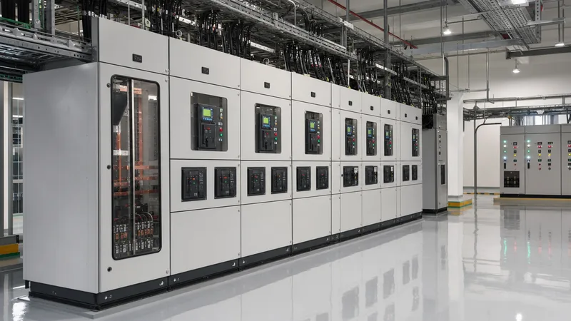
An lv switchboard is an enclosure assembly containing main horizontal and vertical busbars, incoming circuit protective devices, feeder disconnects, metering packages, and control interfaces designed to route bulk electrical power to discrete sub-circuits. Operating below 1000 V AC (typically 400 V, 415 V, or 690 V in 50 Hz systems, and 480 V or 600 V in 60 Hz networks), the assembly safely isolates faults, enables load shedding, and supports maintenance without disconnecting upstream distribution infrastructure.
The functional architecture of low voltage switchboards splits into four primary zones:
- Incomer section: Houses the main incoming air circuit breaker (ACB) or moulded-case circuit breaker (MCCB), instrument current transformers (CTs), voltage transformers (VTs), surge protective devices (SPDs), and digital power quality meters.
- Busbar compartment: Contains high-conductivity electrolytic copper (Cu-ETP) or aluminium alloy conductors running horizontally across the top, centre, or rear of the assembly to carry full line current.
- Functional unit compartments: Dedicated, compartmentalised cubicles housing outgoing motor control starters, feeder circuit breakers, or switch-disconnector fuses.
- Cable and termination zones: Segregated raceways and termination glands where incoming power cables, bus duct trunking, and outgoing distribution feeders land onto copper connection palms.
For large-scale infrastructure, engineers often deploy an integrated HV and LV switchgear setup directly coupled to a transformer secondary, establishing an uninterrupted energy flow from the substation boundary down to final circuit distribution panels.
Low voltage main switchboard forms of internal separation
Internal separation defines the physical partitioning inside a low voltage main switchboard using metallic or non-metallic barriers to prevent accidental contact with live parts and inhibit the migration of internal faults between sections. IEC 61439-2 clause 8.5.101 classifies internal separation into four basic forms, further subdivided into variants based on whether termination points are separated from functional units.
Selecting the appropriate form depends on operational criticality, personnel safety policies, and the required level of live maintenance capability. Higher separation forms prevent an arc flash initiated in a single outgoing tier from migrating into the main horizontal busbar chamber, thereby protecting the rest of the facility from total blackout. For additional safety considerations regarding fault arc containment, review the analysis on arc flash safety and switchgear design.
| Separation Form | Busbars Separated from Functional Units | Functional Units Separated from Each Other | Terminals for External Conductors Separated from Busbars | Terminals Separated from Functional Units | Typical Industrial Application |
|---|---|---|---|---|---|
| Form 1 | No | No | No | No | Small commercial panels, non-critical sub-distribution boards (<250 A) |
| Form 2a | Yes | No | No | No | Commercial building service panels; terminals not separated from busbars |
| Form 2b | Yes | No | Yes | No | Light industrial loads; busbar chamber isolated, terminals grouped together |
| Form 3a | Yes | Yes | No | No | Industrial facilities; outgoing devices segregated, terminals in common zone |
| Form 3b | Yes | Yes | Yes | No | Process plants; functional units segregated, cable entries isolated from busbars |
| Form 4a | Yes | Yes | Yes | Yes (in same compartment) | Heavy manufacturing, utilities; individual terminal chambers per breaker tier |
| Form 4b | Yes | Yes | Yes | Yes (in separate compartment) | Continuous process industries, data centres, hospitals requiring live intervention |
Specifying Form 4b construction ensures that an electrician terminating or testing an outgoing feeder in its dedicated cable chamber is isolated from the main horizontal busbars and adjacent operating circuits, preventing accidental contact or tool drops from creating catastrophic short circuits.
Busbar sizing and thermal withstand calculation for low voltage switchboards
Busbar sizing within low voltage switchboards must satisfy two independent design conditions: continuous full-load current carrying capacity without exceeding allowable temperature rise limits, and mechanical/thermal short-circuit withstand during a bolted fault. Sizing conductors solely based on general thumb rules risks thermal runaway within enclosed switchboards.
Consider an industrial low voltage main switchboard fed by a 2000 kVA, 400 V dry-type transformer with an impedance voltage ($u_k$) of 6.0%. The nominal secondary full-load current ($I_n$) is calculated as follows:
$$I_n = \frac{S}{\sqrt{3} \times U} = \frac{2{,}000{,}000 \text{ VA}}{\sqrt{3} \times 400 \text{ V}} = 2886.8 \text{ A}$$
Selecting an incoming circuit breaker rated at 3200 A covers the nominal transformer capability with expansion allowance. Next, calculate the prospective symmetrical three-phase short-circuit current ($I_{sc}$) at the transformer terminals, assuming an infinite upstream medium-voltage network:
$$I_{sc} = \frac{I_n}{u_k} = \frac{2886.8 \text{ A}}{0.06} = 48{,}113 \text{ A} \approx 48.1 \text{ kA}$$
The switchboard must therefore be rated for a short-time withstand current ($I_{cw}$) of at least 50 kA for a duration of $t = 1.0\text{ s}$. The peak withstand current ($I_{pk}$) per IEC 61439-1 Table 7 requires an asymmetry factor of $n = 2.1$ for fault levels between 20 kA and 50 kA:
$$I_{pk} = 50 \text{ kA} \times 2.1 = 105 \text{ kA}_{\text{peak}}$$
To confirm that the copper busbar will not exceed its allowable temperature under adiabatic short-circuit conditions, evaluate the minimum required cross-sectional area ($S_{min}$) using the adiabatic formula from IEC 60364-5-54:
$$S_{min} = \frac{I_{cw} \times \sqrt{t}}{k}$$
Where $k = 166 \text{ A}\cdot\text{s}^{1/2}/\text{mm}^2$ for bare copper conductors with an initial operating temperature of 70 °C and a maximum transient short-circuit temperature of 180 °C:
$$S_{min} = \frac{50{,}000 \text{ A} \times \sqrt{1.0 \text{ s}}}{166} = 301.2 \text{ mm}^2$$
While $301.2 \text{ mm}^2$ of copper satisfies the short-circuit thermal threshold, continuous current carrying requirements dominate the design. Under IEC 61439-1 Table 6, temperature rise on bare copper busbars inside an enclosure must not exceed 65 K above a standard 35 °C ambient (total maximum temperature 100 °C). For 3200 A natural convection cooling inside an IP42 enclosure, practical busbar engineering requires three flat copper bars of $100 \times 10 \text{ mm}$ in parallel per phase, providing a total cross-sectional area of $3000 \text{ mm}^2$ per phase. Busbar supports must be mechanically spaced (typically 250 mm to 300 mm centres) to withstand the electrodynamic forces generated by the 105 kA peak current.
Protection coordination and circuit breaker selection in an lv switchboard
Protection coordination in an lv switchboard ensures that downstream fault conditions are isolated by the immediate upstream protective device without tripping main incomers or interrupting unaffected branch circuits. Establishing reliable selectivity requires coordinate pairing between Air Circuit Breakers (ACBs), Moulded Case Circuit Breakers (MCCBs), and Miniature Circuit Breakers (MCBs).
Main switchboard incomers require category B circuit breakers equipped with programmable electronic trip units (microprocessor-based protection relays). Category B breakers possess an intentional short-time withstand capability ($I_{cw}$), allowing the breaker to remain closed during a downstream fault for a programmed delay ($t_{sd}$, typically 100 ms to 400 ms). This short-time delay enables downstream category A devices (which trip instantaneously upon reaching their magnetic threshold) to clear the fault locally.
Key protective functions configured on the main incoming breaker include:
- Long-time protection (L / ANSI 51): Guards against thermal overloads; settings adjustable from $0.4 \times I_n$ to $1.0 \times I_n$ with inverse time-delay characteristics.
- Short-time protection (S / ANSI 51): Coordinates discrimination against short-circuit events down the line; adjustable pickup current ($1.5 \times I_r$ to $10 \times I_r$) and definite or $I^2t$ time delays.
- Instantaneous protection (I / ANSI 50): High-level electromagnetic protection that overrides time delays if a bolted fault occurs within the main switchboard busbar compartment itself.
- Ground-fault protection (G / ANSI 51N/51G): Detects low-magnitude phase-to-earth faults that might otherwise fail to trigger phase overcurrent trip units, preventing arcing fires.
For detailed selection methodologies, consult our low voltage circuit breaker sizing guide, or review overall architectural layouts within our low voltage panel engineering guide.
Factory testing and commissioning procedure for a low voltage switch board
A factory routine verification sequence for a low voltage switch board ensures that every manufactured assembly complies fully with verified design parameters, wiring integrity, and insulation safety rules prior to packing and transport. IEC 61439-2 clause 11 mandates that routine testing must be executed on 100% of finished assemblies at the manufacturer's facility.
Testing engineers must execute the following sequential commissioning steps:
- Visual inspection and mechanical check: Verify enclosure degree of protection (IP rating), mechanical clearance distances (minimum 14 mm through air per IEC 61439-1 Table 1 for 8 kV impulse), creepage paths (minimum 16 mm for 690 V insulation), torque-marking of all bolted busbar connections, and operation of interlocks, racking mechanisms, and door latches.
- Dielectric test (power frequency withstand): Apply an AC test voltage between all live phases and the earthed metal frame, as well as between disconnected phases. For a rated insulation voltage ($U_i$) between 300 V and 690 V, apply 1890 V AC RMS (or 2500 V DC) for 5 seconds per IEC 61439-1 Table 8. Verify no disruptive discharge or puncture occurs.
- Insulation resistance verification: Using a calibrated 1000 V DC insulation tester, measure resistance between phases and from each phase to earth. The recorded insulation value must exceed 1000 ohms per volt (minimum 1.0 megohm, though a well-constructed dry board should routinely measure above 100 megohms).
- Protective conductor continuity: Verify electrical continuity between all structural metal parts, withdrawable cassettes, hinged doors, and the main earth bar using a micro-ohmmeter. The maximum resistance from any metallic surface to the earthing terminal must not exceed 0.1 ohms.
- Secondary wiring and operational functional test: Energise auxiliary control circuits at rated control voltage. Verify trip and close coils, undervoltage releases, automatic transfer switch (ATS) logic controllers, analogue/digital metering displays, and safety interlocks. Inject primary or secondary test currents to verify electronic trip unit pickup points.
Next steps: specifying and sourcing
When specifying a project-specific switchboard assembly, project engineers should provide single-line diagrams (SLDs), available prospective short-circuit fault levels ($I_{sc}$), incoming feeder arrangements (bus duct vs cable entries), preferred Form of Separation, and ambient environmental ratings (such as ambient temperature, seismic zones, and required IP enclosures). Discover our engineered low-voltage switchgear solutions and skid-mounted prefabricated transformer substations designed to global IEC and IEEE standards. Submit your single-line schematics directly via our switchgear quotation portal to receive a full engineering evaluation and technical compliance proposal.
Frequently asked questions
What is the difference between an LV switchboard and an LV switchgear?
In IEC terminology, switchgear is an overarching term covering assemblies, breakers, and disconnectors, whereas a switchboard denotes a specific, freestanding distribution assembly containing multiple switching and metering components. In North American ANSI/NEMA standards, switchgear features fully compartmentalised drawout circuit breakers with rear busbar access, whereas switchboards often use front-connected, fixed-mount, or group-mounted overcurrent protective devices.
What is the difference between Form 2b and Form 4b internal separation?
Form 2b separates the main busbars from functional units and provides separated terminals for external conductors, but leaves individual functional units and outgoing cable terminations open to one another. Form 4b encloses each functional unit in its own individual compartment and physically isolates the external cable termination points of every unit from each other and from the busbars.
How is short-time withstand current (Icw) tested on an LV switchboard?
The manufacturer subjects a prototype switchboard frame to high-power laboratory testing where prospective fault currents (such as 50 kA for 1 second) are injected through busbars and bracing systems. The assembly passes if it shows no structural deformation, mechanical breakage, or breakdown of insulation clearances, and successfully passes a post-test dielectric withstand verification.
What copper busbar plating is recommended for industrial switchboards?
Tin plating is the industry standard for general industrial applications, providing effective corrosion resistance, low contact resistance, and prevention of copper oxide formation at joint interfaces. Silver plating is preferred for high-current switchboards (>3200 A) or elevated ambient operating temperatures because silver oxide maintains high electrical conductivity.
Why is neutral conductor sizing critical in low-voltage main switchboards?
Non-linear electronic loads, variable frequency drives, and data equipment produce triplen harmonics (specifically 3rd, 9th, and 15th harmonics) that do not cancel out in the neutral conductor of three-phase systems. Under severe harmonic distortion, neutral currents can exceed phase currents, requiring a 100% or 200% rated neutral busbar to avoid dangerous thermal failure.
Tags: lv switchboard low voltage switchboards low voltage main switchboard IEC 61439 busbar design


