Key takeaways
- A medium voltage breaker operates between 1 kV and 72.5 kV to clear normal load currents and prospective short-circuit faults within three to five cycles.
- Modern distribution systems predominantly specify vacuum interrupters due to their 30,000-operation mechanical endurance and maintenance-free contact design.
- Breaking capacity sizing requires calculating both symmetrical AC fault current and the percentage DC component per IEC 62271-100 clause 6.102.
- Operating duty cycles define thermal and mechanical reclosing limits, with standard auto-reclosing duty specified as O - 0.3 s - CO - 3 min - CO.
- Routine acceptance testing requires contact resistance measurements below manufacturer limits (typically 20 to 45 micro-ohms) and pole discrepancy under 2 milliseconds.
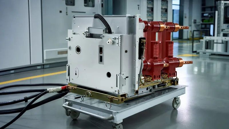
Quick answer: A medium voltage breaker is an automated mechanical switching device engineered to interrupt fault currents and control distribution networks operating between 1 kV and 72.5 kV. Utilizing vacuum bottles or sulphur hexafluoride (SF6) gas chambers, it extinguishes electric arcs within 30 to 80 milliseconds to isolate electrical faults and protect downstream assets.
In commercial, utility, and heavy industrial distribution systems, medium voltage circuit breakers serve as the primary line of defence for transformers, feeder lines, and large rotating machines. These switching units are housed inside modular enclosures detailed in our MV switchgear engineering guide, where they coordinate with digital numerical protection relays and current transformers to detect phase-to-phase short circuits, ground faults, and under-voltage conditions. Sizing a medium voltage breaker requires rigorous analysis of system voltage, continuous current, prospective short-circuit levels, and transient recovery voltages (TRV).
Operating Principles of Medium Voltage Breakers
A medium voltage breaker operates by mechanically separating electrical contacts within a specialised arc-quenching medium upon receiving a trip signal from a protective relay. When the primary contacts part under load or fault conditions, current continues to flow through a metal-vapour or gaseous plasma known as an electric arc. The interrupter must de-ionise this plasma channel and re-establish dielectric insulation faster than the rate of rise of transient recovery voltage (RRTRV) across the open contact gap.
Arc quenching relies on three primary mediums across historical and modern installations:
- Vacuum Interruption: Inside a hermetically sealed ceramic vacuum bottle (internal pressure below 10-5 Pa), contact separation creates a metal vapour arc supported solely by vaporised contact material. At the natural AC current zero, this vapour condenses onto surrounding internal copper-chromium vapour shields within microseconds, restoring dielectric strength across contact gaps as small as 8 mm to 12 mm.
- Sulphur Hexafluoride (SF6): The arc is extinguished inside a pressurised SF6 chamber where the gas molecule absorbs free electrons to form heavy, immobile negative ions. While highly effective for high-voltage transmission, environmental restrictions on fluorinated greenhouse gases have curtailed its use in distribution-tier indoor applications.
- Air Magnetic Interruption: Older medium voltage air breakers force the arc into ceramic arc chutes containing metallic splitter plates using magnetic blowout coils. These bulky assemblies require extensive periodic maintenance and have been almost completely superseded by vacuum technology in installations such as metal clad switchgear.
Medium Voltage Breaker Ratings and Selection Criteria
Specifying a medium voltage circuit breaker requires matching system electrical parameters to standardised manufacturer ratings defined under IEC 62271-100 or IEEE C37.04. Selecting inadequate ratings risks contact welding, explosive catastrophic failure, or insulation flashover during network fault events.
Every installation specification must verify the following core ratings:
- Rated Voltage (Ur): The upper limit of the highest system operating voltage (e.g., 12 kV, 17.5 kV, 24 kV, or 36 kV for standard IEC networks; 4.76 kV, 15 kV, 27 kV, or 38 kV for IEEE systems).
- Rated Insulation Level: Defined by both the power-frequency withstand voltage (Ud, e.g., 28 kV RMS for 1 minute on a 12 kV system) and the rated lightning impulse withstand voltage (Up / BIL, e.g., 75 kV or 95 kV crest per IEC 60071-1 Table 2).
- Rated Continuous Normal Current (Ir): The continuous RMS current a circuit breaker carries indefinitely without exceeding temperature rise limits (typically 630 A, 1250 A, 2000 A, 3150 A, or 4000 A forced-cooled per IEC 62271-1 clause 6.5).
- Rated Short-Circuit Breaking Current (Isc): The highest symmetrical RMS short-circuit current the breaker interrupts at rated voltage, standard across values of 16 kA, 20 kA, 25 kA, 31.5 kA, 40 kA, and 50 kA.
- Rated Short-Circuit Making Current (Ip): The peak prospective current the breaker can safely close against during a fault. Under IEC standards, this equals 2.5 times the symmetrical breaking current at 50 Hz (2.6 times at 60 Hz), accounting for maximum DC offset.
- Operating Sequence (Duty Cycle): The standardised mechanical operating sequence the mechanism executes without refurbishment. The IEC auto-reclosing sequence is O - 0.3 s - CO - 3 min - CO, where "O" represents opening, "CO" represents closing immediately followed by tripping, and the time values represent dead times.
Sizing and Short-Circuit Breaking Capacity: Worked Calculation
Calculating the required breaking capacity of an mv circuit breaker ensures the device clears prospective network faults before thermal and dynamic stresses destroy busbars and connected transformers. The following calculation demonstrates incoming medium voltage breaker sizing for an industrial substation stepped down from a 33 kV utility grid.
Consider an industrial distribution substation with the following design parameters:
- Upstream 33 kV network fault level ($S_{sc,grid}$): 1,000 MVA
- Step-down power transformer rating ($S_n$): 20 MVA
- Voltage ratio: 33 kV primary / 11 kV secondary
- Transformer impedance ($Z_{\%}$): 8.0%
- System frequency: 50 Hz
- Substation operating voltage: 11 kV nominal ($U_r = 12\text{ kV}$ rating class)
Step 1: Determine the grid source impedance referred to the 11 kV secondary busbar:
$$Z_{grid} = \frac{U_{sec}^2}{S_{sc,grid}} = \frac{11^2}{1000} = 0.121\ \Omega$$
Step 2: Determine the transformer impedance referred to the 11 kV secondary:
$$Z_{tx} = \frac{Z_{\%}}{100} \times \frac{U_{sec}^2}{S_n} = \frac{0.08 \times 11^2}{20} = 0.484\ \Omega$$
Step 3: Calculate total prospective fault impedance at the 11 kV main incomer (assuming purely reactive impedances for conservative sizing):
$$Z_{total} = Z_{grid} + Z_{tx} = 0.121 + 0.484 = 0.605\ \Omega$$
Step 4: Calculate the symmetrical three-phase short-circuit breaking current ($I_{sc}$):
$$I_{sc} = \frac{U_{sec}}{\sqrt{3} \times Z_{total}} = \frac{11{,}000}{\sqrt{3} \times 0.605} = 10{,}491\text{ A} \approx 10.49\text{ kA}$$
Step 5: Determine required short-circuit making current peak ($I_p$ per IEC 62271-100):
With a typical system $X/R$ ratio of 14, the peak factor $\kappa$ is 2.55:
$$I_p = \kappa \times \sqrt{2} \times I_{sc} = 1.80 \times \sqrt{2} \times 10.49\text{ kA} \approx 26.7\text{ kA peak}$$
Engineering Selection: The incoming 11 kV circuit requires a standard 12 kV medium voltage breaker. Standard commercial breaking tiers dictate selecting a 12 kV, 1250 A, 25 kA symmetrical breaking capacity breaker with a rated short-circuit making capacity of 63 kA peak. This provides a 138% safety margin over the calculated 10.49 kA fault current, accommodating future parallel generation or utility grid fault level increases.
Technology Comparison: Medium Voltage Vacuum Circuit Breaker vs SF6 and Air
A medium voltage vacuum circuit breaker is the undisputed standard for modern indoor primary and secondary switchgear. The following decision matrix compares the three dominant interruption technologies across operating environments, lifetime maintenance cycles, and operational limits.
| Interrupter Characteristic | Medium Voltage Vacuum Circuit Breaker | SF6 Gas Circuit Breaker | Medium Voltage Air Breakers |
|---|---|---|---|
| Interrupting Medium | High vacuum (< 10-5 Pa) | Sulphur Hexafluoride (0.3 to 0.6 MPa) | Atmospheric air with magnetic blowout |
| Arcing Contact Travel Gap | 8 mm to 14 mm | 25 mm to 65 mm | 100 mm to 250 mm |
| Mechanical Endurance (IEC Class) | M2 class (10,000 to 30,000 ops) | M1 to M2 class (2,000 to 10,000 ops) | Class M0 (1,000 to 2,000 ops) |
| Full Short-Circuit Clearances | 30 to 100 operations | 10 to 25 operations | 3 to 8 operations |
| Environmental Impact & GWP | Zero GWP (closed bottle) | Extremely high (GWP = 23,500) | Zero GWP |
| Switching Overvoltages | Potential current chopping; requires surge arresters for small inductive loads | Negligible current chopping | Low overvoltage generation |
| Routine Interrupter Maintenance | Maintenance-free sealed vacuum bottle | Gas pressure monitoring and leak detection required | Chute de-ashing, contact dressing, alignment |
For high-frequency switching duties such as arc furnaces, capacitor banks, or motor circuits, vacuum technology paired with zinc-oxide surge limiters is standard practice. To examine vacuum bottle construction and contact geometries in detail, reference our technical analysis in the vacuum circuit breaker guide.
Commissioning Procedures and Factory Acceptance Testing
Commissioning procedures verify that a medium voltage circuit breaker's mechanical linkages, trip coils, vacuum bottles, and primary isolation clusters meet factory baseline values before energisation. Testing must follow IEC 62271-100 clause 7 and project site acceptance testing (SAT) protocols.
- Contact Resistance Measurement (Micro-Ohm Test): Inject a minimum of 100 A DC through each closed phase using a four-wire digital low-resistance ohmmeter. Contact resistance must remain within factory-specified limits, typically between 20 $\mu\Omega$ and 45 $\mu\Omega$. Elevated values indicate misaligned tulip contacts or pitted interrupter surfaces.
- Breaker Timing and Motion Analysis: Connect a breaker timing analyser to measure opening time, closing time, bounce duration, and contact stroke speed. Symmetrical opening times must range between 30 ms and 50 ms. Pole-to-pole discrepancy across the three phases must not exceed 2.0 ms during closing and 1.5 ms during opening.
- High-Potential Dielectric Withstand (Hi-Pot): Apply power-frequency AC test voltage across open contacts and phase-to-earth for 60 seconds per IEC 62271-1 Table 1A (e.g., 28 kV AC for a 12 kV rated breaker). Vacuum bottles that have lost integrity will experience dielectric breakdown.
- Secondary Control Circuit and Relay Scheme Verification: Verify the operational limits of shunt trip coils, undervoltage releases, and spring-charging motors across 70% to 110% of nominal auxiliary DC/AC supply voltage, integrating findings with protective relays outlined in our substation protection engineering guide.
- Mechanical Interlock and Racking Checks: Physically verify that draw-out cassettes cannot be racked in or out while the breaker main contacts are in the closed position, preventing live arcing across primary disconnect stabs.
Next steps: specifying and sourcing
When preparing a request for quotation (RFQ) for medium voltage breakers, provide complete project parameters: single-line diagrams, nominal and maximum operating voltages, system frequency, continuous busbar current, BIL ratings, symmetrical breaking capacity, and auxiliary control voltages. Specify whether you require fixed-mount units or draw-out cassettes complete with racking cradles and safety shutters. Review our engineered MV and LV switchgear assemblies and integrated prefabricated transformer substations. For project-specific short-circuit reviews, quotation pricing, and custom breaker cubicle configurations, submit your design drawings directly via our substation quotation portal.
Frequently asked questions
What is the primary function of a medium voltage breaker?
A medium voltage breaker clears excessive fault currents and controls normal electrical loads between 1 kV and 72.5 kV. It extinguishes high-energy electrical arcs inside vacuum or gas bottles to isolate downstream short circuits and prevent distribution equipment destruction.
Why have vacuum interrupters replaced medium voltage air breakers?
Vacuum interrupters have replaced air breakers because they are completely sealed, compact, and virtually maintenance-free. They deliver up to 30,000 operating cycles compared to 2,000 for air-magnetic units, eliminating the need for periodic arc chute cleaning and contact dressing.
What is the difference between rated breaking capacity and rated making capacity?
Rated breaking capacity is the maximum symmetrical RMS current the breaker can safely open and interrupt during a fault. Rated making capacity is the peak prospective current the breaker can close into during an active short circuit, typically 2.5 times higher than the breaking capacity.
How often should a medium voltage circuit breaker undergo routine maintenance?
Medium voltage circuit breakers require visual inspection and lubrication every 12 months, with comprehensive secondary injection, timing tests, and contact resistance testing scheduled every 3 to 5 years. Severe operating conditions or high fault counts demand accelerated maintenance schedules.
What causes current chopping in medium voltage vacuum circuit breakers?
Current chopping occurs when a vacuum interrupter forces alternating current to zero prior to the natural sinusoidal AC zero-crossing point while clearing small inductive loads. This rapid current collapse can produce severe transient overvoltages, requiring surge arresters on motor and transformer feeders.
Tags: medium voltage breaker medium voltage circuit breaker mv circuit breaker medium voltage vacuum circuit breaker medium voltage air breakers


