Key takeaways
- Transformer types are primarily classified by cooling medium, construction architecture, winding configuration, voltage class, and installation environment according to IEC 60076 and IEEE C57.12 standards.
- Dry-type cast resin units provide high fire resistance (Class F1 under IEC 60076-11) making them the primary choice for indoor substations and commercial building transformer applications.
- Liquid-immersed transformers deliver superior thermal dissipation, smaller footprint-to-kVA ratios, and lower initial capital expenditure for outdoor utility and heavy industrial networks.
- Selection parameters require balancing basic insulation level (BIL), impedance percentage (%Z), no-load and load losses, and local environmental classification.
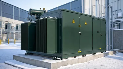
- Pad-mounted and kiosk substations combine distribution transformers with integrated medium-voltage and low-voltage protection for public access and underground reticulation schemes.
Quick answer: The correct type of transformer is determined by cooling medium (oil-immersed versus dry-type cast resin), voltage level, insulation requirements, and operational environment (indoor commercial facility versus outdoor distribution yard). While oil-immersed units offer superior heat dissipation and economic efficiency for bulk outdoor power, dry-type designs provide the non-flammable safety essential for internal commercial installations.
In electrical engineering, matching system parameters to the optimal transformer design prevents premature insulation breakdown, excessive loss penalties, and non-compliance with regional life-safety regulations. Understanding the underlying physical and thermal trade-offs enables procurement engineers, EPC contractors, and plant designers to select equipment that delivers reliability over a typical thirty-year asset lifecycle. To understand basic conversion principles before selecting architectures, review our analysis of the purpose of transformer installations across modern power grids.
Classification: Core and Winding Architectures by Type of Transformer
A transformer operates as either a core-type or shell-type magnetic circuit depending on how the laminated silicon steel surrounds the copper or aluminium windings. In core-type units, cylindrical winding assemblies encircle the vertical limbs of the laminated core, offering straightforward thermal management, high mechanical accessibility, and simpler repair procedures during major maintenance. Shell-type units, conversely, feature magnetic laminations that encircle the electrical coils, offering superior short-circuit bracing and structural rigidity for high-current, low-voltage furnace or heavy industrial duties.
Winding topologies further bifurcate into multi-winding isolation transformers, concentric winding designs, and autotransformers. An autotransformer shares a common electrical winding between its primary and secondary circuits, yielding significant footprint and material cost savings when interconnecting networks with voltage ratios below 2:1. However, because autotransformers lack galvanic isolation, standard two-winding isolation transformers remain mandatory across public distribution networks and standard 3 phase transformer guide architectures to prevent medium-voltage zero-sequence disturbances from migrating to low-voltage equipment.
Cooling Medium: Dry-Type Versus Oil-Immersed Transformers
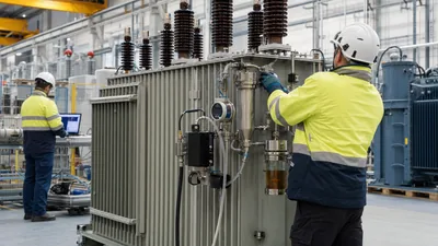
The choice between liquid-immersed and dry-type insulation defines the structural footprint, maintenance schedule, and fire protection profile of any power installation. Oil-immersed transformers circulate mineral oil, synthetic ester, or natural ester fluid (vegetable oil) through the core and coils to achieve dielectric withstand and convective cooling, operating under cooling classifications defined by IEC 60076-2 such as ONAN (Oil Natural Air Natural) and ONAF (Oil Natural Air Forced).
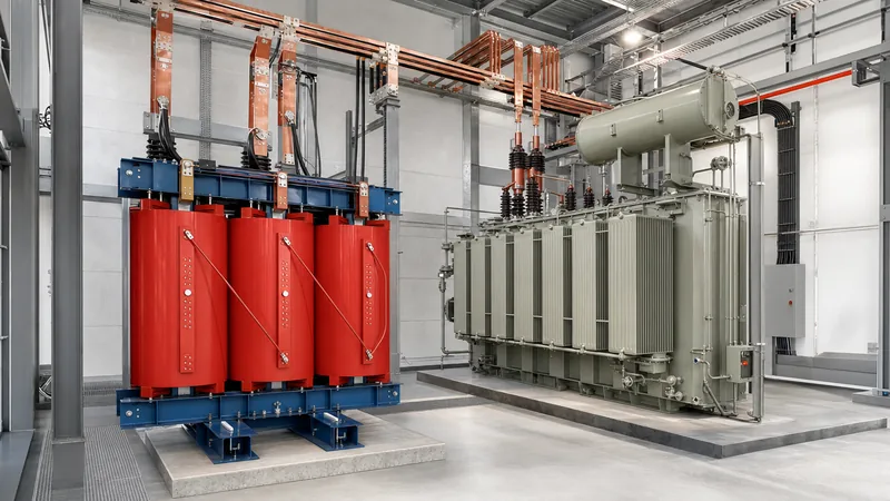
Dry-type units employ Class F (155°C) or Class H (180°C) solid dielectric materials, utilising either vacuum pressure impregnation (VPI) or vacuum cast resin (CRT) techniques to encapsulate the high-voltage coils in epoxy resin. For indoor facilities, cast resin units eliminate fluid-containment sumps and blast walls, operating under IEC 60076-11 environmental Class E2, climatic Class C2, and fire behaviour Class F1 criteria. Consult our dedicated dry type transformer guide for detailed thermal rise thresholds and insulation degradation mechanisms. Liquid units continue to dominate outdoor substations where natural convection to ambient air sustains higher continuous MVA ratings at reduced capital expense.
Primary Types of Transformers: Technical Comparison
Industrial and utility projects evaluate transformers using specific operational limits, physical footprint constraints, and regulatory codes. The decision matrix below compares the standard types across nominal rating, dielectric integrity, efficiency, and typical field applications.
| Type of Transformer | Cooling / Dielectric Medium | Typical Capacity Range | BIL Rating (IEC 60076-3) | Primary Application Environment |
|---|---|---|---|---|
| Liquid-Immersed Distribution | Mineral oil / Synthetic ester | 50 kVA - 3,150 kVA | 75 kV - 170 kV | Utility distribution, outdoor industrial substations |
| Cast Resin Dry-Type | Epoxy resin / Solid air | 100 kVA - 25,000 kVA | 60 kV - 125 kV | Commercial buildings, underground metros, hospitals |
| Pad-Mounted Compartmental | Mineral oil / FR3 natural ester | 75 kVA - 5,000 kVA | 60 kV - 125 kV | Underground residential distribution (URD), retail sites |
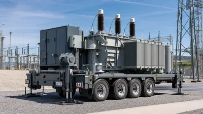
| Substation Power Transformer | Inhibited mineral oil | 5 MVA - 100+ MVA | 170 kV - 550+ kV | Transmission step-down, bulk utility substations |
| Unit Substation / Compact | Dry-type or Liquid-filled | 250 kVA - 4,000 kVA | 60 kV - 125 kV | Factories, mining compounds, containerised energy |
Pad-mounted compartmental transformers house the tank, high-voltage bayonet fusing, and low-voltage cable terminations inside a tamper-resistant, lockable steel enclosure compliant with IEEE C57.12.28 standards. This enclosure removes the need for perimeter chain-link security fencing, establishing pad-mounted designs as the standard interface for commercial office parks, university campuses, and decentralised solar collection rings.
Selecting a Commercial Building Transformer: Life-Safety and Losses
A commercial building transformer must adhere to stringent building life-safety regulations, low audible noise levels, and non-flammable dielectric parameters. Building regulations such as NFPA 70 (National Electrical Code) Article 450 and regional structural codes mandate that oil-filled units installed inside occupied buildings require expensive fire-rated transformer vaults with automatic halon or deluge water-spray suppression systems, liquid containment sills, and dedicated outdoor ventilation louvres.
Consequently, cast resin dry-type transformers serve as the prevailing standard for commercial building installations. These dry units generate minimal toxic gases under electrical fault arcing, are self-extinguishing, and can be situated directly alongside main distribution boards in basement electrical rooms or plant mezzanines. When selecting equipment for multi-storey assets or mixed-use retail complexes, consider the following technical rules:
- Acoustic noise suppression: Commercial environments demand decibel levels lower than factory floors; select units built with stepped lap-joint cores to maintain sound power levels below 55 dB(A) per NEMA TR 1.
- K-factor harmonic rating: Commercial office loads contain heavy non-linear IT infrastructure, LED driver arrays, and variable frequency drives (VFDs); specify K-factor ratings (K-4 to K-13) to prevent neutral conductor overheating and core saturation.
- Energy efficiency mandates: Verify compliance with regional performance tiers, such as Ecodesign Directive EU 548/2014 Tier 2 or US DOE 10 CFR Part 431, minimising both no-load losses (core loss) and load losses (winding resistance loss).
Engineering Sizing Calculation: Specifying KVA and Short-Circuit Impedance
Correct electrical sizing of any transformer type requires evaluating continuous full-load demand, ambient temperature de-rating factors, and secondary fault level constraints dictated by percent impedance (%Z). Below is a verified engineering calculation for sizing a medium-voltage to low-voltage transformer powering an industrial processing building.
Given: Maximum connected load = 1,120 kW at 0.85 lagging power factor; continuous operating load diversity factor = 0.80; anticipated future expansion allowance = 15%; ambient installation temperature = 45°C in an unconditioned plant room (requiring a 5% thermal derate for standard 40°C rated windings).
- Calculate Apparent Power Demand (S_base):
S_base = (Real Power / Power Factor) * Diversity Factor = (1,120 kW / 0.85) * 0.80 = 1,054.1 kVA. - Incorporate Plant Expansion Allowance:
S_expanded = S_base * 1.15 = 1,054.1 kVA * 1.15 = 1,212.2 kVA. - Apply Thermal Derating for 45°C Ambient:
S_required = S_expanded / 0.95 = 1,212.2 kVA / 0.95 = 1,276.0 kVA. - Select Standard Standardised Rating: Select the next standard rating per IEC 60076: 1,600 kVA.
- Determine Fault Current with Selected Impedance (%Z = 6.0%):
Rated low-voltage secondary current at 400 V (three-phase):
I_rated = 1,600 kVA / (sqrt(3) * 0.400 kV) = 2,309.4 A.
Prospective symmetrical short-circuit current (I_sc):
I_sc = I_rated / (%Z / 100) = 2,309.4 A / 0.06 = 38,490 A (38.49 kA).
This fault level demonstrates that the associated low-voltage switchboard must carry a minimum prospective short-circuit withstand rating of 40 kA for 1 second under IEC 61439 criteria. For projects combining local generation or modular distribution, review our guide to unit substation engineering to coordinate primary medium-voltage protection with downstream switchgear.
Factory Acceptance Testing and Sourcing Checklist
A factory acceptance test (FAT) validates that the chosen transformer meets nameplate efficiency, insulation withstand, and dimensional tolerances prior to dispatch. When issuing Requests for Quotation (RFQs) and witnessing manufacturer routine testing per IEC 60076-1 clause 7.2, electrical engineers must enforce the following verification criteria.
- Winding Resistance Measurement: Verified on all tap positions using a four-wire Kelvin bridge to ensure balanced phase resistance and confirm conductor sizing.
- Voltage Ratio and Vector Group Verification: Checked across all off-circuit tap changer (OCTC) or on-load tap changer (OLTC) positions to confirm correct angular phase displacement (e.g., Dyn11 or Ynd1).
- Impedance Voltage and Load Loss Testing: Measured at rated frequency and current, corrected to reference temperatures (75°C for oil-immersed, 120°C/145°C for Class F/H dry-type).
- Separate-Source AC Withstand & Induced Overvoltage: Applied overvoltage tests to verify ground-wall and inter-turn dielectric integrity under transient overvoltages.
- Partial Discharge Measurement: Mandatory for cast resin units; levels must remain below 10 pC at 1.3 times rated phase-to-ground voltage per IEC 60076-11 clause 14.3.1.
Next steps: specifying and sourcing
To obtain an accurate quotation for your project, compile your single-line diagram, nominal primary and secondary voltages, BIL requirements, tap-changer specifications, and site environmental constraints. Explore our engineered ranges of dry type transformers, outdoor oil immersed transformers, and integrated pad-mounted transformers manufactured to strict IEC and IEEE criteria. Our engineering team assists consultants, EPCs, and contractors worldwide with project-specific thermal, acoustic, and electrical design calculations. Contact our technical specialists directly or submit your full RFQ documentation through our transformer quotation portal.
Frequently asked questions
What is the most common type of transformer used in buildings?
Cast resin dry-type transformers are the most common units used in commercial and public buildings. They eliminate oil leakage risks, comply with fire safety codes without expensive vault construction, and require minimal maintenance.
What is the difference between an autotransformer and an isolation transformer?
An isolation transformer features electrically separated primary and secondary windings, providing galvanic isolation and filtering line disturbances. An autotransformer shares a single common winding, making it smaller and cheaper but without electrical isolation between primary and secondary circuits.
Can an oil-immersed transformer be installed indoors?
Yes, but it requires strict structural fire protection measures under building codes like NFPA 70. These include reinforced three-hour fire-rated vaults, oil containment bunds, blast relief panels, and automatic fire extinguishing systems, which often makes dry-type units more cost-effective.
What does K-factor mean for a commercial building transformer?
K-factor measures a transformer's ability to handle the heating effects of harmonic currents generated by non-linear electronic loads. A standard transformer has a K-1 rating, while commercial building designs with heavy server or lighting loads often require K-4, K-9, or K-13 ratings.
What is the life expectancy of an industrial distribution transformer?
The typical design life of an industrial distribution transformer is 25 to 35 years when operated within standard thermal limits. Operating below rated winding hot-spot temperatures and performing routine dielectric maintenance can extend asset lifespan beyond 40 years.
Tags: type of transformer commercial building transformer distribution transformer dry type transformer oil immersed transformer