Key takeaways
- Arc flash mitigation focuses on reducing fault clearing time, lowering available short-circuit currents, and deflecting thermal blast energy away from personnel.
- Reducing clearing time from 500 ms to 45 ms using high-speed optical arc detection drops incident energy on a 480 V bus from over 22 cal/cm² to below 2 cal/cm².
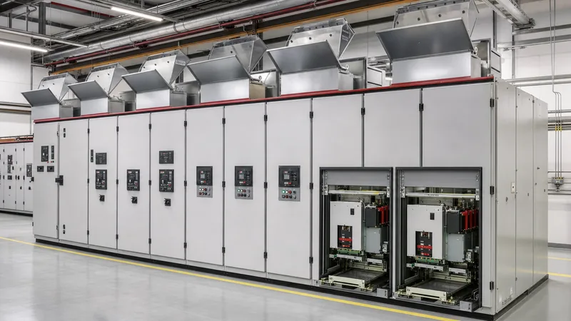
- Passive mitigation relies on structural containment and pressure relief vents governed by IEC 62271-200 Annex AA and IEEE C37.20.7.
- Active mitigation solutions include zone-selective interlocking (ZSI), maintenance switches (ERMS), and current-limiting devices that do not alter switchgear enclosure dimensions.
- Specifying arc flash protection at the engineering stage reduces lifecycle personal protective equipment (PPE) requirements and limits internal arc damage to repairable levels.
Quick answer: Arc flash mitigation encompasses engineering design techniques and active protection devices that reduce the incident thermal energy released during an internal arcing fault, redirect blast pressure away from personnel, or eliminate human exposure during switching operations. These methods lower incident energy levels below standard safety thresholds defined in NFPA 70E and IEEE 1584.
An electric arc inside an electrical assembly can vaporise copper conductors instantaneously, generating blast pressures exceeding 100 kN/m² and temperatures upwards of 19,000 °C. While basic safety relies on personal protective equipment (PPE), modern power engineering prioritises upstream engineering controls. By addressing clearing times, fault energy thresholds, and enclosure dynamics, facilities can transform high-risk switchgear rooms into controlled, low-incident-energy environments. Understanding how to select and apply the right arc flash solutions protects assets, ensures regulatory compliance, and safeguards technical personnel during critical switching routines.
Hierarchy of Arc Flash Mitigation Techniques
Arc flash mitigation techniques follow the standard engineering hierarchy of controls: elimination, substitution, engineering controls, awareness, and administrative controls. In electrical power distribution, elimination means de-energising equipment before working on it, which remains the mandated baseline under NFPA 70E Article 130.2. However, because operational testing, troubleshooting, and continuous process requirements often make complete de-energisation impossible, engineers focus heavily on engineering controls.
Engineering-based arc flash mitigation solutions divide into two main categories: active systems and passive systems. Active systems detect the fault condition and clear it as rapidly as possible to limit total dissipated energy ($I^2t$). Passive systems do not alter clearing times; instead, they contain, channel, and vent the acoustic pressure wave, toxic gases, and superheated plasma out of the switchgear room via dedicated plenums. Understanding the foundational physics of an arcing event is essential when selecting equipment; our detailed analysis in what is arc flash examines plasma generation, arcing fault current mechanics, and human boundary calculations.
Calculating Incident Energy Reduction: Worked Engineering Example
Incident energy is directly proportional to the total arcing duration, meaning reducing protection clearing time produces an immediate, linear reduction in thermal exposure. IEEE 1584-2018 Clause 4 provides the mathematical framework for calculating arcing current ($I_{arc}$) and incident energy ($E$) based on open-air, box, and electrode configuration parameters. Consider a standard 480 V industrial low-voltage switchboard fed by a 2,000 kVA, 5.75% impedance transformer.
The engineering variables for this installation are defined as follows:
- System voltage ($V$): 480 V (three-phase, 50/60 Hz)
- Available bolted three-phase fault current ($I_{bf}$): 42 kA RMS symmetrical
- Working distance ($D$): 610 mm (24 inches)
- Electrode configuration: Vertical conductors inside a metal box (VCB)
- Busbar gap ($G$): 32 mm
Using IEEE 1584-2018 equations, the calculated arcing current ($I_{arc}$) is approximately 23.4 kA. We now evaluate two protection scenarios to see the impact of active arc flash mitigation:
Scenario A (Standard Upstream Overcurrent Protection): The upstream circuit breaker relies on standard selective coordination with a short-time delay setting of $t = 0.50$ seconds (500 ms) to coordinate with downstream feeders. The resulting incident energy is:
$$E_A \approx 26.8 \text{ cal/cm}^2$$
At 26.8 cal/cm², personnel require heavy Category 4 PPE, and the thermal blast causes structural destruction of the busbar compartments and feeder sections.
Scenario B (High-Speed Optical Arc Flash Relay Integration): The switchgear is fitted with point optical sensors in the breaker, busbar, and cable compartments, wired to an optical detection unit paired with an instantaneous trip coil. The optical detection occurs within 2 ms, and total breaker opening time is 40 ms, giving a total clearing time of $t = 0.042$ seconds (42 ms). Re-evaluating the incident energy at 610 mm:
$$E_B \approx 2.25 \text{ cal/cm}^2$$
By implementing this high-speed clearing technique, the incident energy drops by over 91%, bringing the switchboard into a standard Category 1 PPE envelope and preventing structural bus destruction.
Active vs Passive Arc Flash Mitigation Solutions
Active and passive arc flash solutions address different physical aspects of an electrical fault, requiring engineers to balance capital cost, physical footprint, and protection speed. The table below compares the five most common active and passive engineering solutions specified in medium-voltage and low-voltage industrial distribution networks.
| Mitigation Solution | Operating Mechanism | Clearing / Reaction Time | Incident Energy Impact | Enclosure / Space Requirement |
|---|---|---|---|---|
| Optical Arc Detection Relays | Active: Combines optical light sensors with phase-current overcurrent supervision | 1 ms to 2 ms detection; total fault clearance in 40 ms to 60 ms | Reduces incident energy by up to 90%, often keeping values below 4 cal/cm² | Minimal: Small relay footprint inside the LV control compartment |
| Energy-Reducing Maintenance Switch (ERMS) | Active: Temporarily removes intentional time delays on upstream trip units during servicing | 30 ms to 50 ms (mechanical breaker speed dependent) | Reduces incident energy during maintenance windows to Category 1 or 2 levels | Zero external footprint: Local control switch or digital input |
| Fast-Acting Arc Quenching Systems | Active: Pyrotechnic or magnetic switch creates a zero-impedance three-phase bolting to earth/bus | Total clearing within 4 ms to 5 ms, quenching the arc before peak pressure | Near-complete elimination of thermal output (< 1.2 cal/cm²) | Requires dedicated cabinet module or breaker compartment space |
| Arc-Resistant Enclosures (IEC 62271-200) | Passive: Reinforced hinges, labyrinth gaskets, and top-mounted pressure relief flaps | Independent of trip time; redirects blast energy upwards/outwards | Thermal and pressure energy directed away from the operator at the front/sides | Requires minimum 800 mm ceiling clearance or dedicated exhaust plenums |
| Current-Limiting Fuses & Breakers | Passive/Active: Melts fuse element or forces contacts open during the first quarter-cycle | Clears high fault currents in under 8 ms (sub-cycle clearing) | Substantially restricts let-through energy ($I^2t$) under fault conditions | Standard enclosure sizing; limited to lower-rated circuits or feeder branches |
To establish comprehensive protection across distribution networks, consulting engineers often combine methods—for instance, housing active sensor schemes within standard metal clad switchgear to guarantee safety both during operational switching and maintenance inspections.
Arc-Resistant Switchgear Design and Gas Ducting
Arc-resistant switchgear represents the primary passive engineering solution for containing arc blast forces without requiring sub-cycle electrical clearing. Standards such as IEC 62271-200 (Annex AA) and IEEE C37.20.7 classify equipment based on operator accessibility under arcing conditions. Switchgear rated Type 2B provides protection around the entire perimeter (front, sides, and rear) even while the low-voltage control door is open for instrument servicing.
When an internal arc occurs within an enclosed compartment, air temperature rises to thousands of degrees in milliseconds, causing an explosive rise in volume and pressure. Without engineered pressure relief, doors rip off hinges and sheet steel splits at weld points. Arc-resistant enclosures manage this through three coordinated design features:
- Reinforced compartmentation: Heavy-gauge steel barriers (2.5 mm to 3.0 mm) compartmentalise the breaker, main busbars, and cable terminations, preventing cross-compartment arc propagation as specified in IEC 61439 low-voltage switchgear and IEC 62271 standards.
- Pressure relief flaps: Spring-loaded or shear-pinned panels on top of the cubicle open at specific overpressures (typically 10 kPa to 20 kPa), allowing gas expansion upward away from floor personnel.
- Exhaust ducts and plenums: Sealed sheet-steel ducts collect the expanding hot gases and vent them safely through an external building wall to an unoccupied outdoor zone.
Designing an exhaust plenum requires careful architectural integration. The duct exit must be positioned at least 3 metres above grade and away from personnel walkways, building air intakes, and flammable utility piping.
Modern Active Arc Flash Solutions: Detection and Interlocking
Active arc flash mitigation techniques eliminate the delay imposed by upstream protection coordination curves without compromising selective tripping. In conventional systems, an upstream main breaker waits 300 ms to 500 ms to allow a feeder breaker to isolate a local branch fault. During an arc event on the bus, this intentional delay generates catastrophic damage.
To solve this, advanced active systems utilise two distinct technologies:
Zone Selective Interlocking (ZSI): In a ZSI scheme, downstream feeder relays communicate with upstream trip units via hardwired signal loops or high-speed digital communications (such as IEC 61850 GOOSE). If a fault occurs on a downstream branch, the branch relay sends a blocking signal to the main breaker, commanding it to respect its intentional time delay. However, if an arcing fault occurs on the main busbar between the main and branch devices, the branch relays see no fault current and send no restraint signal. The main breaker trips instantly (typically within 30 ms to 50 ms). For complex multi-source setups, integration with substation protection schemes ensures that bus couplers and inter-tier ties trip selectively without manual intervention.
Optical and Multi-Sensor Systems: Optical systems monitor compartments using point sensors or flexible bare-fibre-optic loops. Because flash photography, fluorescent lighting flickers, or switching arcs inside circuit breakers can cause optical false alarms, high-integrity systems require dual-criteria tripping. The relay only issues a trip command if it receives simultaneous signals from:
- An optical detector detecting the characteristic high-intensity light flash; and
- An instantaneous overcurrent pickup indicating current exceeding normal load thresholds (typically set at 1.2 to 1.5 times nominal rating).
By pairing dual-criteria optical relays with fast-operating circuit breakers, total fault duration drops below 50 ms, limiting physical damage to superficial busbar scorches that can be wiped clean during turnarounds.
Engineering Specification Checklist for Arc Flash Protection
When preparing procurement specifications or tender documents for medium-voltage and low-voltage assemblies, engineers must define performance-based safety requirements rather than generic safety requests. An incomplete specification leaves critical boundaries open to contractor interpretation, often resulting in equipment with dangerous incident energy ratings.
Incorporate the following checklist items into your switchgear specifications to guarantee thorough arc flash mitigation:
- Design Standards: Specify exact compliance with IEC 62271-200 Annex AA (for medium voltage) or IEEE C37.20.7, indicating accessibility type (e.g., Accessibility Type 2B, AFLR: Front, Lateral, Rear).
- Internal Arc Classification (IAC): Define the prospective arc current and duration rating, such as IAC AFLR 31.5 kA for 1.0 second.
- Active Sensor Coverage: Mandate point optical sensors or continuous fiber sensors in each distinct high-voltage compartment: breaker cradle, cable termination chamber, and main busbar run.
- Tripping Criteria: Require dual-criteria activation (light plus overcurrent supervision) to prevent nuisance tripping, with a maximum relay decision time of 2 ms.
- Maintenance Mode Integration: Require an external Energy-Reducing Maintenance Switch (ERMS) with local blue LED indication and auxiliary dry contacts for SCADA monitoring on all main incomers rated 1,200 A and above.
- Remote Racking Capabilities: Mandate provisions for motorised or umbilical-cord remote racking devices, permitting operators to rack circuit breakers between the Disconnected, Test, and Connected positions from outside the flash protection boundary.
- Plenum & Venting Path: Detail the building interface, specifying whether switchgear includes self-contained top-venting absorbers or requires engineered exhaust ducting to the building exterior.
Next steps: specifying and sourcing
Mitigating arc flash hazards requires clear coordination between switchgear structural design, protective relay settings, and architectural room layouts. When preparing a project for tender, supply your complete single-line diagram, transformer impedances, available upstream short-circuit capacities, and preferred enclosure accessibility ratings. Explore our engineered line of HV and LV switchgear and integrated prefabricated substations to discover fully type-tested assemblies built to international IEC and IEEE standards. For technical assistance with short-circuit calculations, relay coordination, or custom arc duct designs, contact our engineering team via the contact page or submit your tender documents directly through our quotation inquiry page.
Frequently asked questions
What is the primary goal of arc flash mitigation?
The primary goal of arc flash mitigation is to lower the incident thermal energy released during an electrical arcing fault. This protects personnel working near the equipment from severe burns, limits equipment destruction, and ensures compliance with NFPA 70E and IEEE 1584 safety boundaries.
How does reducing clearing time affect incident energy?
Reducing clearing time directly and linearly decreases incident energy, as thermal energy is proportional to the fault duration ($E \propto t$). For example, dropping the clearing time from 500 ms to 45 ms reduces thermal exposure by over 90%, turning a hazardous blast into an easily survivable event.
What is the difference between active and passive arc flash mitigation?
Active mitigation systems detect faults and rapidly disconnect power or extinguish the arc using fast relays, circuit breakers, or quenching switches. Passive mitigation systems, such as arc-resistant enclosures, contain and divert the physical pressure and heat away from operators without changing fault duration.
What is an Energy-Reducing Maintenance Switch (ERMS)?
An Energy-Reducing Maintenance Switch is an active safety control that temporarily bypasses the intentional time delays of an upstream circuit breaker. When an electrician services energized gear, switching on the ERMS forces the breaker to trip instantaneously if a fault occurs, reducing incident energy.
Can older switchgear be retrofitted with arc flash mitigation solutions?
Yes, older switchgear can be retrofitted with active arc flash solutions without replacing enclosures. Facilities commonly install optical arc-detection relays, digital trip units with ERMS capability, zone-selective interlocking networks, or motorised remote-racking accessories to lower risk.
Tags: arc flash mitigation arc flash solutions arc flash mitigation solutions arc flash mitigation techniques switchgear safety


