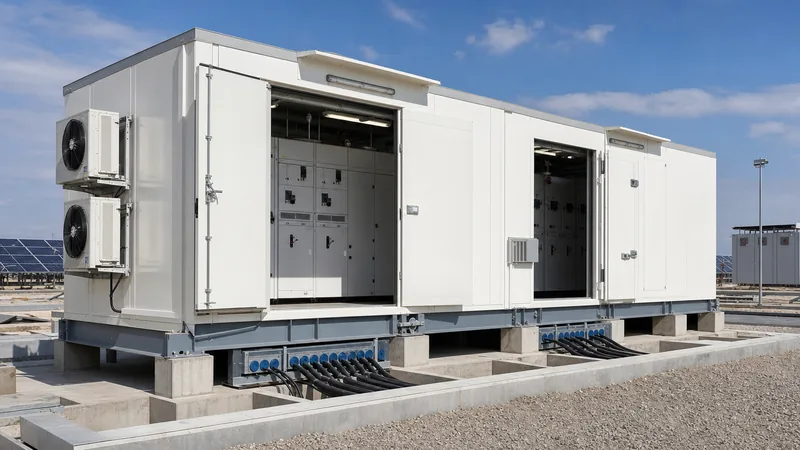
Key takeaways
- A modular substation building reduces on-site construction schedules by 50% to 70% compared to conventional masonry control rooms by shifting assembly to a factory-controlled environment.
- Structural enclosures must satisfy IEC 62271-202 and local building standards (such as ASCE 7 or Eurocode 3) for wind shear, seismic zone ratings, and floor deflection limits under heavy switchgear loads.
- HVAC equipment sizing requires calculating both peak external solar gain and internal sensible heat rejection from medium-voltage switchgear busbars, protection relays, and DC uninterruptible power supplies.
- Standardised cable transits and bottom-entry gland plates maintain an IP54 or NEMA 3R/4 ingress rating while mitigating the ingress of moisture, dust, and rodents into medium-voltage compartments.
- Integrated factory acceptance testing (FAT) allows complete functional interlocking and SCADA communication loop verification between protection relays and switchgear before site delivery.
Quick answer: A modular substation building is a factory-fabricated, transportable structural enclosure housing medium-voltage switchgear, protection and control panels, DC battery systems, and communication equipment. Pre-commissioned on a structural steel base skid prior to transport, it reduces on-site electrical installation timelines by up to 70% while complying with IEC 62271-202 and IEEE standards for utility-scale solar, wind, and battery storage plants.
Utility-scale renewable energy installations require rapid deployment in remote, harsh environments where on-site civil works face significant labor shortages, weather delays, and quality control risks. Traditional brick-and-mortar substation control rooms often become the critical-path bottleneck during substation development. Deploying a prefabricated modular substation building resolves these site constraints by consolidating civil, structural, and electrical works into an integrated manufacturing schedule, yielding pre-tested assemblies that require only foundation anchoring and external cable terminations upon delivery.
Engineering Architecture of a Modular Substation
A modular substation is engineered around a structural steel base frame designed to support the dynamic and static loadings of heavy electrical equipment during crane lifting, transport, and long-term operation. The primary base skid utilises heavy longitudinal wide-flange beams (typically HEB or ASTM W-shapes) braced with structural channel cross-members. Deflection of the base skid is strictly controlled to no more than L/1000 under full operational equipment load to prevent mechanical binding of medium-voltage circuit breaker draw-out mechanisms.
Wall and roof assemblies typically consist of insulated sandwich panels with non-combustible polyisocyanurate (PIR) or mineral wool cores, clamped or welded between structural steel purlins. For harsh desert, coastal, or high-humidity renewable energy corridors, panel coatings must comply with ISO 12944 corrosivity categories (C4 or a standard unit), utilising polyurethane topcoats over epoxy primers on hot-dip galvanised sheet steel. Thermal insulation typically targets an overall heat transfer coefficient (U-value) below 0.35 W/m²K to limit air-conditioning power consumption in extreme ambient conditions ranging from -40°C to +55°C.
Below the equipment floor, engineers integrate either a bottom false-floor plenum or a walk-through cable basement. False floors employ removable, heavy-duty anti-static calcium-sulphate or steel-encapsulated access tiles rated for point loads exceeding 4.5 kN, allowing low-voltage control and DC cabling to run segregated from medium-voltage power cables in line with electromagnetic compatibility (EMC) best practices.
Modular Integrated Substation Control Enclosures vs Brick-and-Mortar
Modular integrated substation control enclosures provide distinct civil, technical, and operational advantages over field-erected concrete masonry units (CMU), particularly for renewable collectors where commissioning schedules are penalised under strict power purchase agreements.
The following table provides a technical and economic comparison between field-constructed buildings and factory-built modular control buildings:
| Evaluation Criterion | Brick-and-Mortar Control House | Modular Substation Building |
|---|---|---|
| Civil Construction Time on Site | 16 to 28 weeks (weather dependent) | 2 to 4 weeks (pad or pier foundation only) |
| Factory Integration & Pre-wiring | 0% (all wiring installed on site) | 90% to 95% fully terminated at factory |
| Protection & Control FAT | Limited to individual panels | Complete integrated relay-switchgear loop FAT |
| Foundation Requirements | Full perimeter concrete footings & slab | Concrete piers or perimeter grade beam |
| Seismic & Wind Design Compliance | Site-specific structural engineering | Engineered to ASCE 7 / IBC / Eurocode standards |
| Fire Resistance Ratings | 2 to 4 hours standard masonry | 1 to 2 hours with certified mineral wool core |
| Relocatability / Asset Salvage | Non-relocatable (demolished on decommissioning) | 100% crane-liftable and transportable |
| Total Project Capital Expenditure | Baseline (high local labor risk) | 15% to 25% lower total installed cost |
While masonry structures offer inherent multi-hour passive fire endurance without specialised coatings, their lengthy civil construction lifecycle introduces project schedule risk. Conversely, a factory-assembled enclosure isolates electrical assembly from site weather delays, allowing foundation works and switchgear manufacturing to proceed in parallel. For detailed insights on control panel layouts inside these enclosures, consult the modular substation control house engineering guide.
HVAC Thermal Sizing and Internal Climate Control
Accurate HVAC sizing within a substation control building prevents premature failure of protection microprocessors and prevents thermal derating of switchgear busbars. Medium-voltage switchboards and auxiliary power systems generate steady heat loads that must be evacuated continuously, even under high ambient solar radiation.
Consider an actual calculation for a 33 kV renewable collector substation control room with dimensions of 12.0 m (length) × 4.0 m (width) × 3.2 m (height):
- Equipment Heat Dissipation: A 6-panel 33 kV vacuum switchboard (rated at 1250 A, carrying nominal 800 A solar plant output) rejects approximately 650 W per panel at full load: 6 × 650 W = 3,900 W.
- DC Auxiliary Systems: Battery charger and 110 V DC battery bank float charging load reject approximately 1,200 W.
- Relay & Communication Panels: Protection, RTU, and SCADA racks reject approximately 1,400 W.
- Internal Sensible Heat Subtotal: 3,900 W + 1,200 W + 1,400 W = 6,500 W (6.5 kW).
- Building Envelope Heat Transfer: At a design ambient temperature of 45°C and an internal setpoint of 25°C (ΔT = 20 K), with wall and roof U-values of 0.38 W/m²K over 182 m² of external surface area: Q_transmission = 182 m² × 0.38 W/m²K × 20 K = 1,383 W.
- Solar Radiation & Safety Factor: Factoring peak roof solar absorption and a 15% safety factor yields an additional solar/ambient load of 2,617 W.
- Total Required Cooling Capacity: 6.5 kW + 1.38 kW + 2.62 kW = 10.5 kW (approximately 3.0 tons of refrigeration / 36,000 BTU/hr).
To ensure high operational availability, specifying redundant dual-redundant (N+1) wall-mounted air conditioning units with automatic lead-lag controllers is mandatory. If one compressor fails or enters a defrost cycle, the secondary unit assumes 100% duty, preventing internal temperature spikes that could trigger protective relay trips under the procedures outlined in our substation protection schemes guide.
Equipment Layout and Power Integration Architecture
A well-planned layout inside a prefabricated electrical substation ensures operator safety, compliance with minimum electrical clearances, and straightforward maintenance access under IEC 61936-1 and NFPA 70 (NEC Article 110.26 / 490).
Medium-voltage switchgear is typically positioned along one longitudinal wall. The rear clearance behind rear-accessible cubicles must measure at least 900 mm to 1000 mm for maintenance, whereas front operating aisles require a minimum width of 1500 mm to 2000 mm to allow circuit breaker withdrawal carts to manoeuvre without blocking personnel egress routes. All doors serving electrical rooms must open outward and feature anti-panic push bars (panic hardware) for rapid egress under emergency conditions.
The control and instrumentation area accommodates protection relay panels, revenue metering cubicles, SCADA remote terminal units (RTUs), and fiber-optic patch panels. Power quality and network stability criteria demand close integration with plant controls, as discussed in the renewable energy grid integration guide. Direct current (DC) power systems—consisting of valve-regulated lead-acid (VRLA) or lithium iron phosphate (LFP) battery banks paired with dual float chargers—occupy a separate partitioned room or an exhaust-ventilated zone compliant with EN 50272-2 to prevent hydrogen gas accumulation.
Cable transits through the building envelope require transit frames with elastomer sealing modules (such as Roxtec or Hawke frames) rated for IP66 and certified for 120 minutes of fire resistance (EI 120). These transits provide gas-tight and water-tight sealing around medium-voltage single-core XLPE cables and multi-core control cables, preventing water ingress from ground trenches into the switchgear cable compartments, which represent a common source of partial discharge described in our medium-voltage switchgear guide.
Factory Assembly, Testing, and Site Commissioning Sequence
The core value of a prefab substation building lies in executing integration and verification activities within a controlled manufacturing facility prior to dispatch.
Factory assembly and commissioning follow an established multi-stage sequence:
- Structural Base and Superstructure Fabrication: The base frame is submerged-arc welded, dimensional tolerances are verified, and steel surfaces undergo abrasive blast cleaning to ISO 8501-1 Sa 2.5 before application of the protective industrial coating system.
- Cladding and Interior Architectural Fit-out: PIR wall panels, roof membrane systems, fire-rated doors, anti-static raised flooring, and cable trays are installed and grounded to the common base earth bar.
- Equipment Staging and Rigging: Medium-voltage switchgear, low-voltage AC/DC boards, battery racks, and automation cabinets are anchored directly to structural unistrut floor beams.
- Inter-panel Cabling and Busbar Splicing: Factory technicians bridge busbar shipping splits with silver-plated copper links torqued to manufacturer specifications, then run auxiliary power, current transformer (CT), and voltage transformer (VT) secondary wiring.
- Integrated Factory Acceptance Testing (FAT): Functional testing includes 2 kV AC insulation resistance checks, primary/secondary injection tests, breaker close/trip timing, interlocking logic, SCADA telecontrol verification, and pressurisation testing of fire suppression systems.
- Transport Separation and Packaging: Large enclosures exceeding road freight dimensional limits (typically 3.5 m to 4.2 m wide) are divided at engineered split lines, sealed with heavy-duty weather shrouds, and fitted with certified lifting lugs for multi-point crane transport.
- Site Reassembly and Final Acceptance Testing (SAT): Upon arrival at the renewable site, modules are hoisted onto concrete pier foundations, bolted together at structural split flanges, weather-sealed, and re-tested for insulation integrity before energisation.
Procurement and Engineering Specification Checklist
Engineers preparing an engineering, procurement, and construction (EPC) specification for a modular substation building should incorporate the following technical parameters to avoid project variations:
- Structural and Environmental Design Criteria: Specify wind speed resistance (e.g., 160 km/h per ASCE 7-16), seismic design category (e.g., Category D / zone 4), ground snow loading, and external corrosivity category (ISO 12944 C5 for coastal or industrial environments).
- Building Dimensional and Shipping Constraints: Define maximum allowable footprint, module split locations, maximum shipping transport envelope dimensions, and dedicated lifting trunnion/crane lug load ratings.
- Floor Loading Capacity: State required dead load and live load ratings; minimum 10.0 kN/m² distributed load and 5.0 kN point load for medium-voltage switchgear sections.
- Fire Integrity and Safety Standards: Enclosure fire rating (EI 60 or EI 120 per EN 13501), automatic clean-agent fire suppression (e.g., FK-5-1-12 / Novec 1230), aspirating smoke detection systems (VESDA), and emergency exit doors with panic hardware.
- Electrical Earthing Network: Copper earth tape sizing (minimum 40 mm × 5 mm or 50 mm × 6 mm hard-drawn copper bar) providing a closed ring bonded to the steel skid at intervals not exceeding 6.0 m.
- Penetrations and Sealing: Frame-based modular mechanical transits for power cables, auxiliary wiring, and fiber optics with spare capacity for at least 25% future expansion.
Next steps: specifying and sourcing
Procuring a dependable modular substation building requires clear coordination between civil site constraints, mechanical climate systems, and electrical architectures. To accelerate engineering reviews, submit your electrical single-line diagram (SLD), general layout preferences, environmental parameters, and utility connection requirements to an experienced manufacturing partner. Explore our integrated prefabricated transformer substations, modular medium- and low-voltage switchgear assemblies, and utility battery energy storage systems. When you are ready to review project scope, foundation layouts, and lead times, request a comprehensive quotation directly at our substation quote portal.
Frequently asked questions
What is a modular substation building?
A modular substation building is an engineered, factory-assembled transportable enclosure that houses electrical equipment including medium-voltage switchgear, control panels, and auxiliary power systems. It is constructed, pre-wired, and tested in a manufacturing plant before being delivered to site as a plug-and-play assembly.
What is the typical delivery and installation lead time for a prefab substation?
Factory design, fabrication, equipment integration, and testing typically require 12 to 20 weeks depending on switchgear complexity. Once delivered to the project site, structural placement, inter-module joining, and cable terminations are completed within two to four weeks.
How does a modular substation control building handle HVAC redundancy?
Most specifications require dual-redundant (N+1) industrial wall-mount HVAC units with automated lead-lag controllers. The system alternates operation between the two units to equalize wear while ensuring 100% cooling backup if one unit trips, protecting critical electronic relays.
Can a modular substation building accommodate medium-voltage arc-resistant switchgear?
Yes, modular buildings are designed to accommodate arc-resistant switchgear by incorporating roof-penetrating arc exhaust ducts, top-mounted pressure relief flaps, or structural blast plenums that vent dangerous arc-flash gases safely outside the occupied building envelope.
What foundations are required for a modular substation building?
Because the structural skid provides internal rigidity, modular buildings do not require continuous poured-concrete slabs. They are commonly supported by concrete piers, strip footings, or helical screw piles spaced along the perimeter and under heavy equipment loads.
Tags: modular substation building modular substation prefabricated electrical substation modular integrated substation control enclosures substation control building


